Final adjustment, Optional horizontal fixed-arm installation, Installation – Kuryakyn 3990 BLACK ERGO III ADJUSTABLE CRUISE MNTS w/ TRIDENT DUALLY PEGS User Manual
Page 5
PAGE
5
FINAL ADJUSTMENT:
NOTE:
Additional adjustment of the Ergo III Adjustable Cruise
Mounts can be made for Mount angle and leg room. If
additional adjustment is needed follow the STEPS below.
STEP 18
Additional Mount angle adjustment: Loosen the four screws from
STEP 7
. Turn the two Set Screws on the bottom clamp-half clockwise
to increase the mount angle. Turn the screws counterclockwise to lower
the angle. Adjust the Set Screws evenly, then tighten the four clamp-
half screws.
STEP 19
Additional leg room adjustment: Loosen the four screws from
STEP 7
. Carefully
slide the mount along the engine guard until you get the desired position. Tighten the
four screws.
OPTIONAL HORIZONTAL FIXED-ARM INSTALLATION:
STEP 20
On the clutch-side of the bike. Remove the 1/2” Screw, Small Flat Washer, and
Large Flat Washer that secures the Rotating Arm to the Mount. FIG 1 on PAGE 6
Set them aside, they will be re-used. Remove the Rotating Arm, Helix and End Cap
from the mount. The inside of the Arm and Helix are marked with an “L”. Refer to
PIC 12 and 14.
STEP 21
Remove the Spring, Steel Bushing, and Brass Bushing. Set these aside, they will
NOT be reused. FIG 2 on PAGE 6
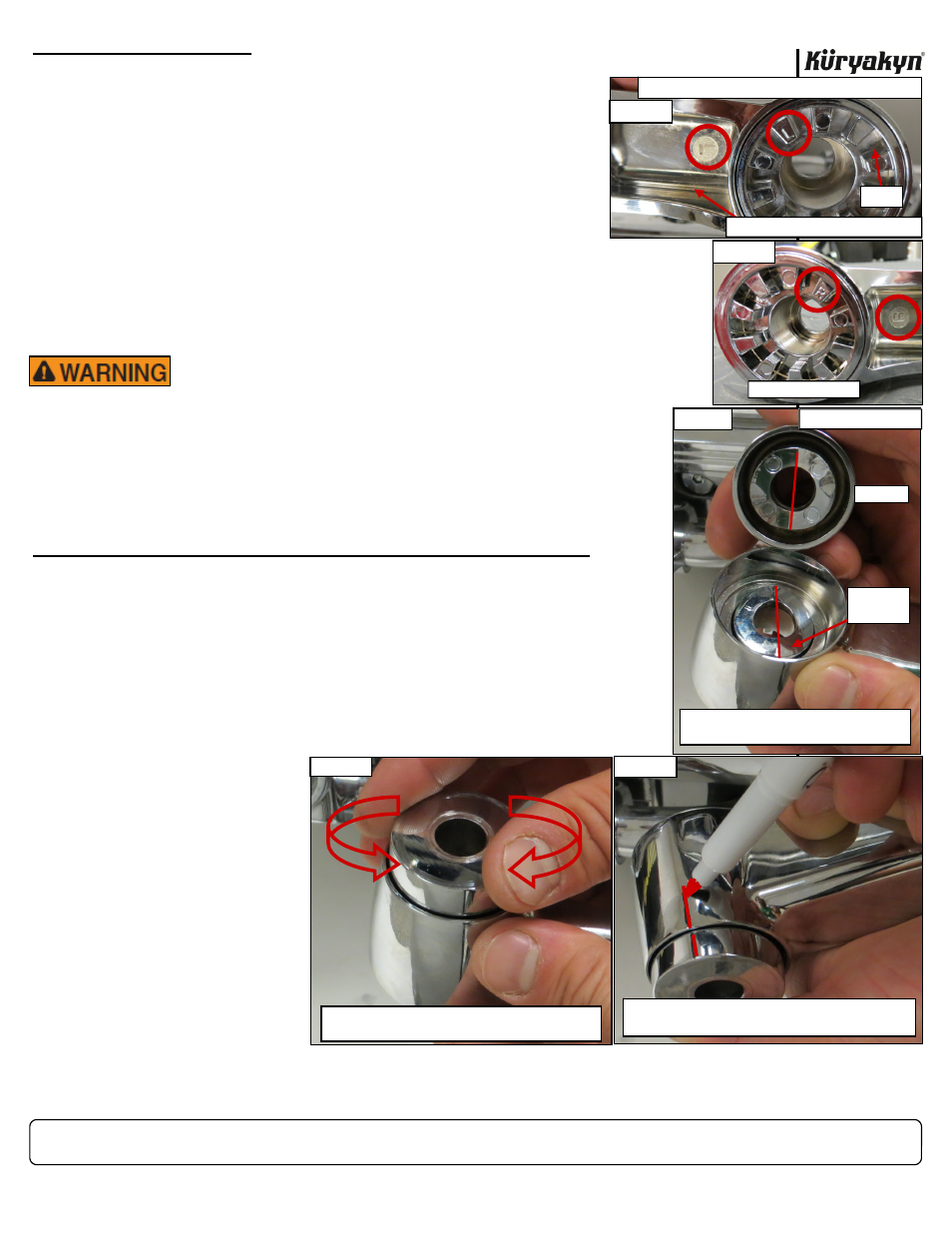
STEP 22
Position the Helix in the
Rotating Arm EXACTLY
as shown in PIC 12. PIC
13 shows the right side.
STEP 23
Hold the Helix in place in
the Rotating Arm and
position the End Cap
over the nose of the He-
lix. PIC 14 Turn the End
Cap until it settles into
place on the nose of the
Helix as shown in PIC
15.
STEP 24
Holding
everything
in
place, make a mark on
the End Cap and Rotating
Arm with a non-permanent marker as shown in PIC 16.
BLACK ERGO III ADJUSTABLE CRUISE MNTS w/ TRIDENT DUALLY PEGS
INSTALLATION
-cont.-
BRAKE-SIDE (RIGHT)
PIC 13
PIC 12
POSITION THE HELIX IN THE ARM EXACTLY AS SHOWN
HELIX
CLUTCH-SIDE (LEFT) ROTATING ARM
PIC 15
TURN THE END CAP TO ALIGN IT WITH THE NOSE OF
THE HELIX
SECURELY HOLD THE HELIX, ROTATING ARM AND END
CAP TOGETHER. MAKE A MARK ON THE END CAP AND ARM
PIC 16
SECURELY HOLD THE HELIX, ROTATING ARM AND END
CAP TOGETHER. MAKE A MARK ON THE END CAP AND ARM
THE ROTATING ARM CAN BE POSITIONED IN A WAY THAT
GREATLY DECREASES CORNERING CLEARANCE WHICH
MAY CAUSE LOSS OF CONTROL RESULTING IN SERI-
OUS INJURY OR DEATH. ENSURE THAT THE ROTATING
ARM IS POSITIONED PARALLEL TO OR ABOVE THE EN-
GINE GUARD WHEN IN THE UNLOADED POSITION. RE-
MOVE YOUR FEET FROM THE FOOTPEG WHEN COR-
NERING TO AVOID LOSS OF CONTROL.
PIC 14
CLUTCH-SIDE (LEFT)
POSITION THE END CAP OVER THE NOSE OF
THE HELIX
END CAP
NOSE OF
HELIX