Universal wiring & relay kit, perch mount, Installation, Install the switch-mount-half – Kuryakyn 2203 UNIVERSAL WIRING & RELAY KIT, PERCH MOUNT User Manual
Page 2
UNIVERSAL WIRING & RELAY KIT, PERCH MOUNT
-cont.-
INSTALLATION
INSTALL THE SWITCH-MOUNT-HALF:
NOTE:
The Switch-Mount-Half assembly replaces the existing clamp-half on either
side of the handlebars; it features a Switch with wiring that will be routed
along the underside of the handlebars. Determine which side will work best for
your handlebar set-up. The Switch MUST NOT interfere with the proper
operation of the motorcycle.
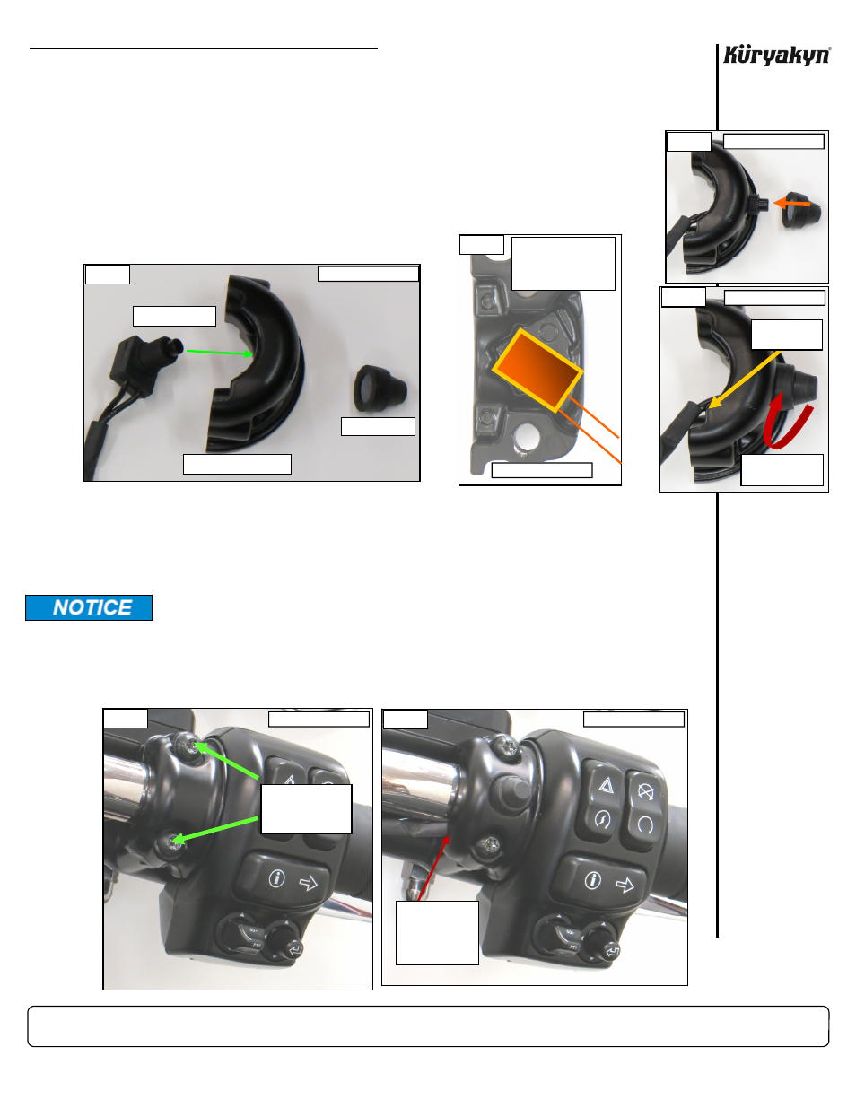
STEP 2
Refer
to
PICs 1, 2, 3, and 4. Insert the included Driving Light Switch into the included
Switch-Mount-Half; align the Switch in the rectangular recess so that the wires will exit
through the bottom notch when it is installed; secure with the included Rubber Boot as
shown. Set the assembly within arms reach of the work area.
STEP 3
Refer
to
PIC 5. Remove the existing screws (and washers) from the existing clamp half; save the
screws, they will be reused.
An extra set of hands will be helpful in securing the master cylinder or clutch lever assembly once the
screws and clamp half have been removed.
STEP 4
Refer
to
PIC 6. Hold the new Switch-Mount-Half assembly in position, route the wiring through the
bottom notch, align the screw holes, and begin the two screws in their threads. Ensure that the hand
controls are positioned correctly and the wires will not be pinched, then tighten the screws; tighten
the top screw first, then the bottom.
PAGE
2
Avoid damage to the motorcycle. Protect painted surfaces with a soft cloth or
service cover.
PIC 5
REMOVE THE
SCREWS,
(WASHERS), AND
CLAMP HALF
BRAKE-SIDE (RIGHT)
ENSURE WIRES
DO NOT GET
PINCHED WHEN
CLAMP IS
TIGHTENED
PIC 6
BRAKE-SIDE (RIGHT)
THREAD BOOT
ONTO SWITCH
PIC 4
WIRE ROUTES
TO BOTTOM
PIC 3
INSERT SWITCH
PIC 1
RUBBER BOOT
SWITCH-MOUNT-HALF
ALIGN SWITCH IN
RECESS SO WIRES
EXIT THE BOTTOM
NOTCH
BRAKE-SIDE (RIGHT)
BRAKE-SIDE (RIGHT)
BRAKE-SIDE (RIGHT)
PIC 2
BRAKE-SIDE (RIGHT)