HYDAC HDA 5500 User Manual
Page 14
13
display
Setting
Setting
range
Pre-
setting
device
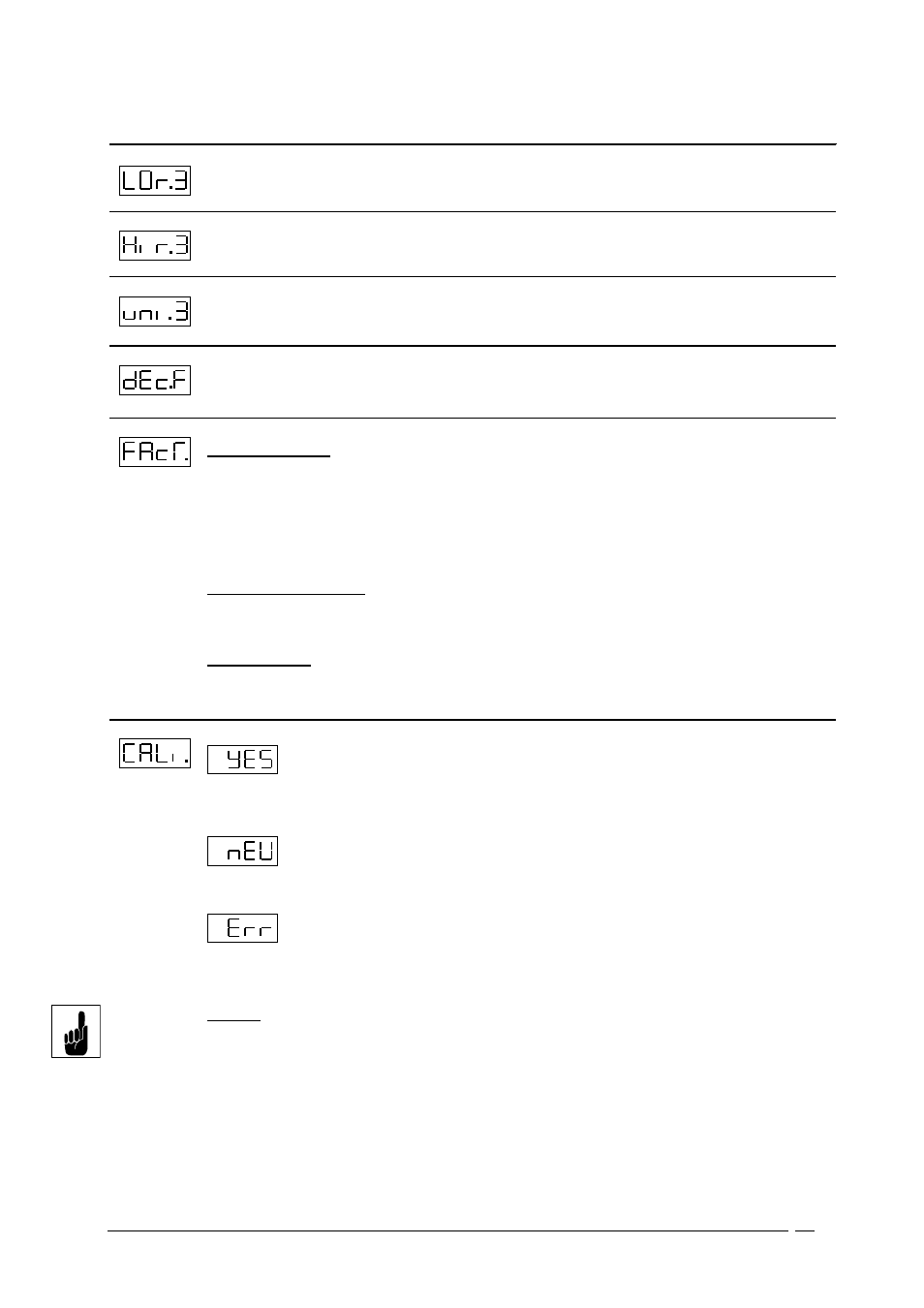
Lower display range (Low Range) Sensor 2
Lower display range limit
-999..9899
0.0
HDA 5500 - 1 - X - XX - XXX
Upper display range (High Range) Sensor 2
Upper display limit
-899..9999
10.0
HDA 5500 - 1 - X - XX - XXX
LED – light indicator Sensor 2
ON
OFF
On
Off
On
HDA 5500 - 1 - X - XX - XXX
decimal place for correction factor
(only availible with frequency/counter function)
0..0.000
0.0
HDA 5500 - 2 - X - XX - XXX
correction factor (frequency/counter function)
Flow measurements:
Settings:
f = (Fakt.) * Qmax / 60 (Hz)
Qmax : maximum flow of turbine in l/min
Fakt. : correktion factor of the turbine (Impulse/l).
decimal place to set in dEcF.
Display:
Flow = (f x 60) / FacT in l/min
Frequency measurements:
To display the frequency in Hz, follow settings must
be done:
dEc.F = 0 and FAcT. = 60
Counter function:
Settings :
decF = 0 und FacT = 1
0..9999
0.0
HDA 5500 - 2 - X - XX - XXX
Calibration of sensor zero point (Calibrate)
The actual pressure is saved as the new zero
point.This is possible in the range +/-2,5% of the
unit’s nominal pressure.
appears in the display when a calibration is carried
out in the permissible range, otherwise
is displayed.
This function is useful, for example, if there is always
a residual pressure in the system which should be
displayed as 0 bar.
Warning:
Following a zero point adjustment, for example, on a
600 bar unit, a pressure of up to 15 bar will be
displayed as 0 bar. Before any work is carried out on
the hydraulic system, ensure that the system is de-
pressurised.
YES/ NO
NO
For all devices