Surface mount dip switches – Grayhill DIP Switches: Surface Mount 90HB Series User Manual
Page 2
Series
Terminal Style: W = Gull Wing, J = J-Bend
RoHS compliant
90HBW02PRT
Packaging: R = Tape and reel packaging (750 switches/reel)
Blank = Tube packaging (each tube is 19.5" long)
Seal: P = Polyimide Seal
Blank = No Seal
Number of Positions: 02 through 10
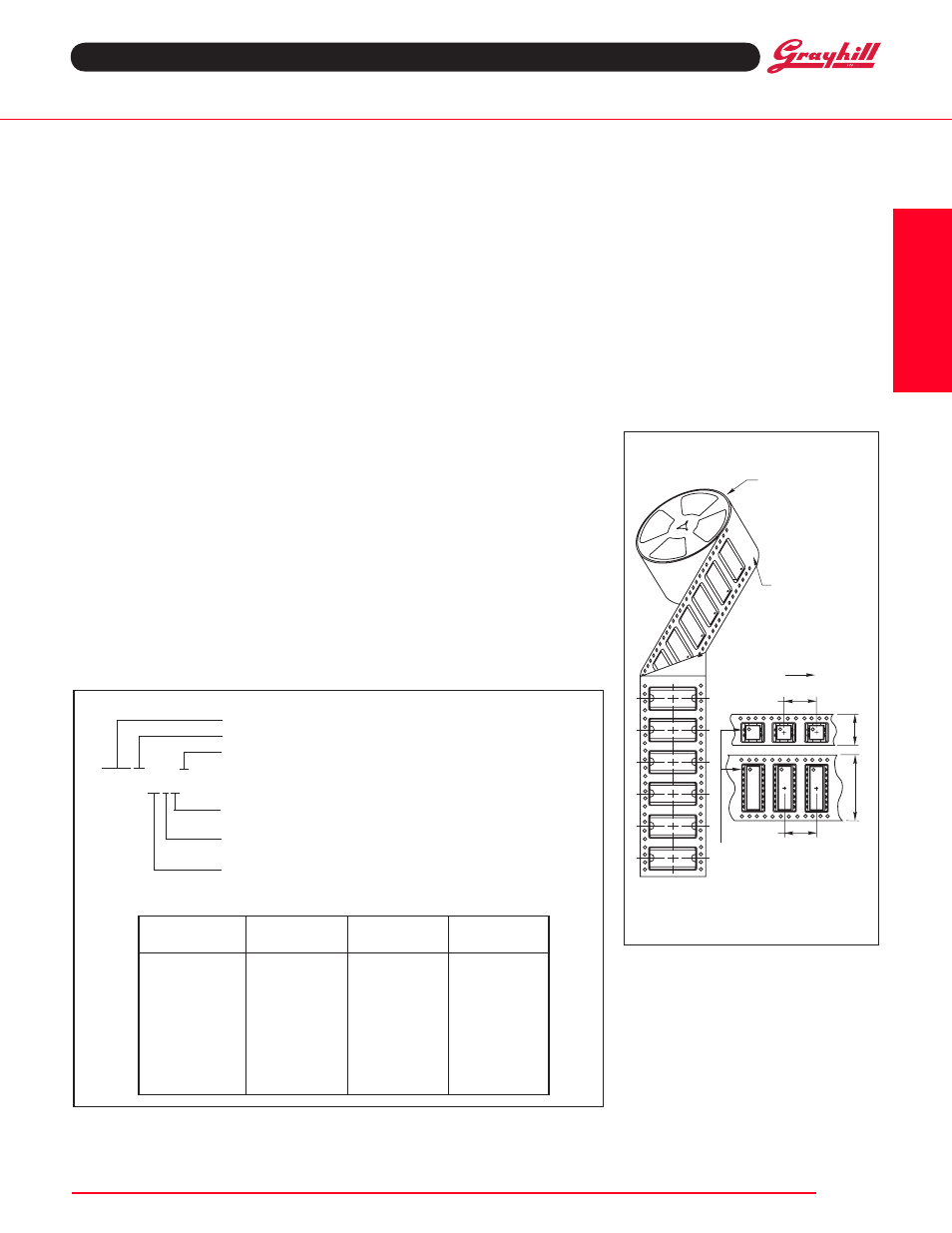
Surface Mount DIP Switches
Meets requirements of
EIA 481-2 or EIA 481-3
Each reel has a 15.750 inch (390 mm)
minimum leader and a 6.30 inch (160 mm)
minimum trailer.
TAPE AND REEL PACkAGING
13 INCH
DIAMETER REEL
DIRECTION
OF FEED
24mm
TAPE
16mm
32 &
44mm
TAPE
16mm
PIN ONE LOCATION
CONDUCTIVE
PLASTIC EMBOSSED
TAPE
SpecificationS
electrical Ratings
Make-and-break current Rating: 2,000
operations per switch position at these resistive
loads:10 mA, 30 Vdc; or 10 mA, 50 mVdc; 10 mA,
50 mVdc; or 25 mA, 24 Vdc; or 100 mA,6 Vdc.
contact Resistance: (measured at 10 mA, 50
mVdc). Initial: 20 mohms maximum, After Life:
100 mohms maximum
insulation Resistance: Minimum, at 100 Vdc
between adjacent closed contacts and also
across open switch contacts.
initial (Mohms): 5,000, After Life (Mohms):
1,000
Dielectric Strength: Minimum voltage (AC
RMS) measured between adjacent closed
contacts and also across open switch
contacts.
lnitial: 500 volts, After Life: 500 volts
current carry Rating: 3A maximum rise of
20°C
Switch capacitance: 2 pF at 1 megahertz
Mechanical Ratings
Where Grayhill performance is superior, the MIL
spec is listed in parentheses.
Mechanical Life: 2,000 operations per switch
position
Vibration Resistance: Per Method 204, Test
Condition B , 1mS opening (10 mS allowed)
Mechanical Shock: Per Method 213, Test
Condition A. 1mS opening (10 mS allowed)
thermal Shock Resistance: Per specification;
no failures; passes contact resistance.
terminal Strength: Per specification
thermal aging: 1,000 hours at 85°C; no
failures.
environmental Ratings
Meets all requirements of MIL- S-83504**.
operating temperature Range: -40°C to +
85°C
Storage temperature Range: -40°C to +
85°C
Moisture Resistance: Per MIL-STD-202,
Method 106.
Soldering information
Solderability: Per MIL-STD-202, Method 208
Soldering Heat Resistance: Per MIL-S-83504,
six second test.
Recommended processing temperature:
220°C–230°C (1 pass—260°C maximum)
processing position: Switch is to be processed
with all actuators in the closed (on) position as
shipped.
fluxing: Per EIA RS-448-2 with flux touching
switch body.
cleaning: Passes immersion test using water/
detergent. Acceptable solutions include 1-1-1
trichlorethane, freon, (TF, TE, or TMS), isopropyl
alcohol, detergent (140°F maximum). Terpene
acceptable for Series 90 only. Solutions which are
not recommended include acetone, methylene
chloride, freon TMC. High pressure aqueous
cleaning is not recommended.
Materials and finishes
Shorting Member (Ball): Brass, gold-plate
over nickel barrier.
Base contacts: Copper alloy, gold-plate
over nickel barrier.
terminals: Copper alloy, matte tin plated over
nickel barrier.
non-conductive parts: Thermoplastic
(uL94V-O)
tape and Reel packaging
tape Seal integrity: Passes gross leak test
using 125°C flourinert for 20 seconds minimum.
Reference MIL-STD-202, Method 112
tape Seal: Polyimide film
oRDeRing infoRMation
Available from your local Grayhill Distributor. For prices and discounts, contact a local Sales Office,
an authorized local Distributor or Grayhill.
** Note: 100% matte tin terminal plating does not meet MIL-S-83504 for lead content.
No. of
Length
Length
Number
Positions
Inches
Metric
Per Tube
2
.270"
6,9 mm
60
3
.370"
9,4 mm
47
4
.470"
11,9 mm
37
5
.570"
14,5 mm
31
6
.670"
17,0 mm
26
7
.770"
19,6 mm
23
8
.870"
22,1 mm
20
9
.970"
24,6 mm
18
10
1.070"
27,2 mm
16
DiP
6
DIP
Switches
Grayhill, Inc. • 561 Hillgrove Avenue • LaGrange, Illinois 60525-5997 • uSA • Phone: 708-354-1040 • Fax: 708-354-2820 • www.grayhill.com