Grayhill DIP Switches: Surface Mount 90HB Series User Manual
Series 90hb, Surface mount dip switches, Circuitry
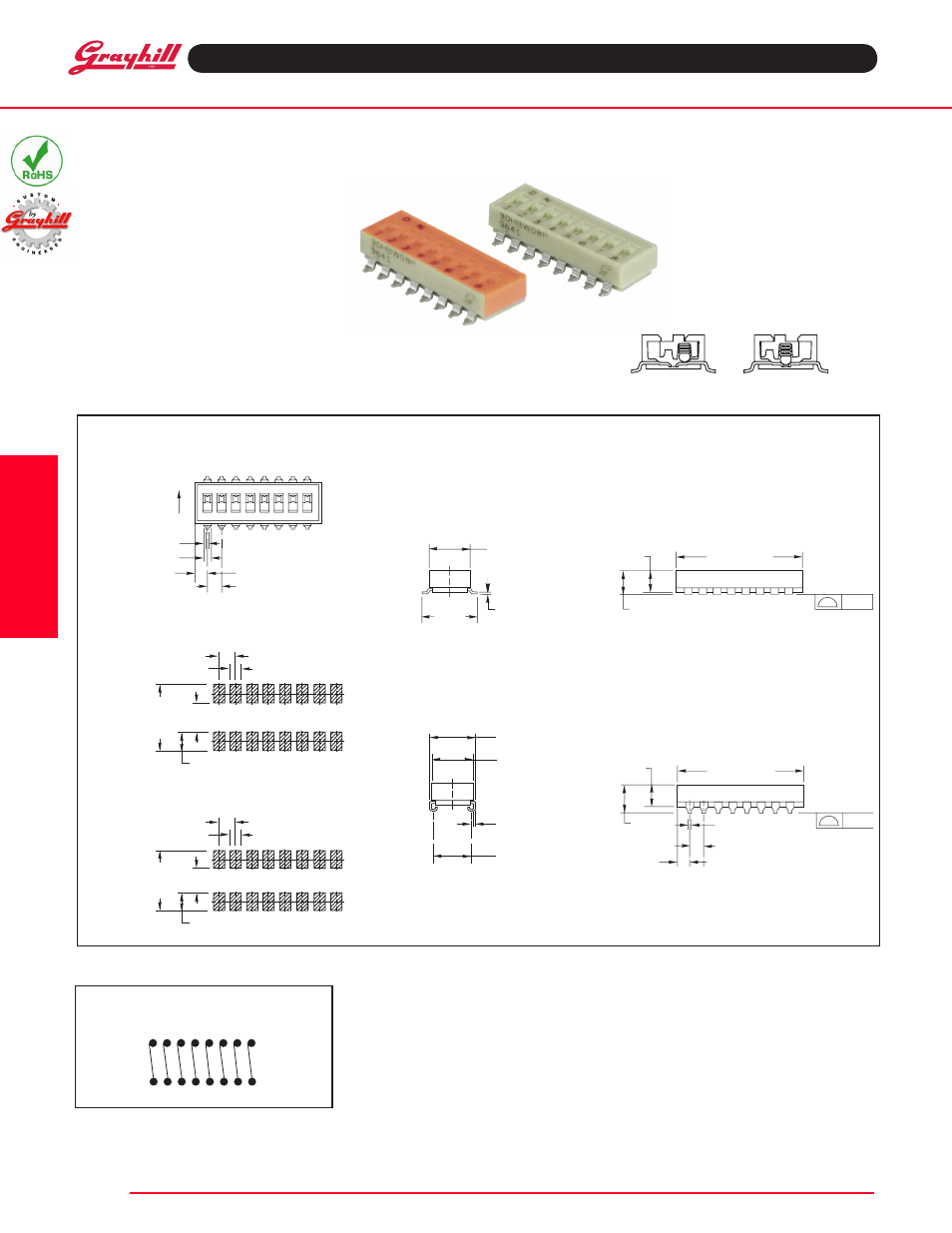
1 2 3 4 5 6 7 8
O N
.020 ± .002
(0,51 ± 0,05) TYP.
.052 ± .002
(1,32 ± 0,13) TYP.
.085 ± .005
(2,16 ± 0,13) TYP.
.100 ± .005
(2,54 ± 0,13)
TYP.
C
L C
L
LENGTH ± .010 (0,25)
SEE CHART
.160 ± .005
(4,19 ± 0,13)
.220
(5,59)
MAX.
.085 ± .005
(2,16 ± 0,13)
TYP.
.020 ± .002
(0,51 ± 0,05) TYP.
.100 ± .010
(2,54 ± 0,25) TYP.
C
L C
L
.320 (8,13)
MAX.
.290 (7,37)
MAX.
.012 ± .001
(0,30 ± 0,03)
TYP.
.250 ± .010
(6,35 ± 0,25)
.290 (7,37)
MAX.
.012 ± .002
(0,30 ± 0,05)
.395
± .010
(10,03
± 0,25)
LENGTH ± .010 (0,25)
SEE CHART
.160 ± .005
(4,19 ± 0,13)
.190
(4,83)
MAX.
.004
(0,10)
.004
(0,10)
SWITCH IS PACKAGED
AS SHOWN HERE
WITH ALL
POSITIONS ON
.350
(8,90)
TYP.
.150 (3,81) TYP.
.100 (2,54) TYP.
.100 (2,54) TYP.
.070 (1,78) TYP.
C
L C
L
.500
(12,7)
TYP.
.250 (6,35) TYP.
.125 (3,18) TYP.
.100 (2,54) TYP.
.070 (1,78) TYP.
C
L C
L
SerieS 90HB
SPST, Low Profile
FeATUreS
• Compatible with SMT Assembly,
Including Infrared Reflow and
Vapor-Phase
• Reliable Spring and Ball Contact
DIMENSIONS
In inches (and millimeters)
Top View–Gull Wing
CIRCuITRy
As viewed from the top of the switch in the
positions shown in the drawing.
Recommended PC Pad Dimensions–Gull Wing
Recommended PC Pad Dimensions–J-Bend
Gull Wing
J-Bend
DiP
5
Surface Mount DIP Switches
Grayhill, Inc. • 561 Hillgrove Avenue • LaGrange, Illinois 60525-5997 • uSA • Phone: 708-354-1040 • Fax: 708-354-2820 • www.grayhill.com
DIP
Switches