Standard keypads, Orientation of modules, Printed circuit board layout – Grayhill Keypads 82 Series User Manual
Page 4: Circuit diagrams
Grayhill, Inc. • 561 Hillgrove Avenue • LaGrange, Illinois 60525-5997 • USA • Phone: 708-354-1040 • Fax: 708-354-2820 • www.grayhill.com
Standard Keypads
Keyboards and Keypads
orientation oF moDuleS
A module, depending on circuitry, may not be
symmetrical. Rotating it 180° will result in a
different pin location. Please note the button
PrinteD CirCuit BoarD laYout
This layout provides the horizontal printed circuit board layout as viewed from the top side of
the PC board. Turning end to end will result in a different pin location. However, the dimensional
relationship will remain the same.
lightable modules–per drawing below.
This drawing indicates the layout to be used for a 6 button module with light sources mounted
two ways: the lamps for the upper 3 buttons are mounted from the top or component side of the
board, and the lamps for the lower 3 buttons are mounted by the easy replacement method. (See
also Light Source and Lamp Mounting.) Light sources, when mounted from the top side of the
board, must be mounted before the keyboard modules; when mounted, lamp should extend no
more than .250" (6,35 mm) above the board.
unlighted module
lightable module
C
L
C
L
C
L
.
488 – .003
(12,40 – 0,08)
TYP.
.687 – .003
(17,45 – 0,08)
.687 – .003
(17,45 – 0,08)
HOLE TO
ACCOMMODATE
.032 (0,81) DIA.
PIN
.045 – .002
(1,14 – 0,05)
TYP.
(8 PLACES)
.687 – .003
(17,45 – 0,08)
.244 (6,20) TYP.
.090
(2,29)
TYP.
.500 – .003
(12,7 – 0,76)
.094
– .010
(2,39
– 0,25)
identification, the pin location for the desired
circuitry, and the direction of mounting. It
is important to use this information when
designing a printed circuit board layout and
when communicating with Grayhill. See Ordering
Information–Special Keyboard Modules on the
next page.
C
L
C
L
C
L
C
L
.687 ± .003
(17,45 ± 0,08)
.687 ± .003
(17,45 ± 0,08)
.270 ± .003
(6,86 ± 0,08)
.112
± .003
(28,45
± 0,08)
TYP.
HOLE TO
ACCOMMODATE
.032 (0,81) DIA.
PIN
.170 (4,32)
RECOMMENDED
DIA. HOLE
ACCOMMODATES
LAMP IN EASY
REPLACEMENT
MOUNTING
DIMENSIONS ARE DEPENDENT ON
LAMP SOURCE. APPROXIMATELY
.020 (0,51) AND .100 (2,54) APART
FOR A T-1 LAMP OR LED
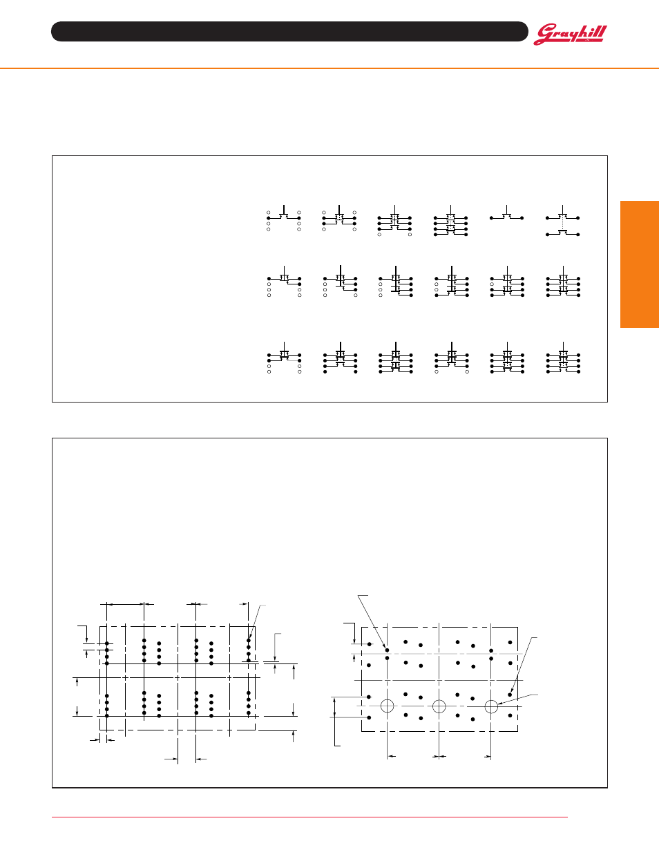
CirCuit DiagramS
The bottom view of the line drawings shows
number (A1, A2, etc.) next to the pin locations
of each switch section. These pin numbers
are directly related to the circuit diagrams.
For example, if the switch under Button A of a
standard module were SPST, the pins would
be located at the "#2" Position. If the module
were a lightable one with SPST circuitry, the
pins would be located at the "#1" Position. If
other locations are desired, specify them.
The coded circuits shown are suggested
possibilities and each button may carry a
different circuit. Location of active pins on each
button may be varied to conform with layout of
the printed circuit board. Up to a 7-bit code is
possible under each button.
Combinations of simple circuitries are also
possible as shown in the sample diagrams.
Standard modules
lightable modules
Coded Circuitry–to 7 Bits/Button
other Possible Circuit Configurations
2
2
3
2
3
2
1
2
3
4
1
2
3
4
1
2
3
4
1
2
3
4
1
1
1
4
1
4
C
C
C
C
C
C
C
C
C
C
SPST
2PST
3PST
4PST
SPST
2PST
Note: Coded switches are constructed so that common (C) is made after all other contacts.