Special function rotary switches, Dimensions specifications, Description – Grayhill Special Function Rotary Switches 50 Series User Manual
Page 3: External differences, Isolated position
Grayhill, Inc. • 561 Hillgrove Avenue • LaGrange, Illinois 60525-5997 • USA • Phone: 708-354-1040 • Fax: 708-354-2820 • www.grayhill.com
Rotary Switches
Special Function Rotary Switches
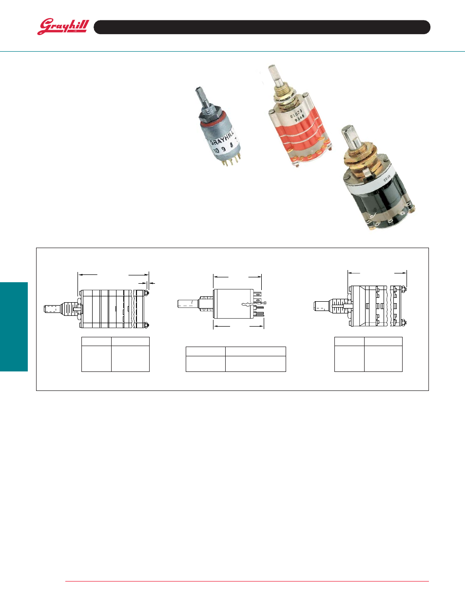
DIMENSIONS
SPECIFICATIONS
Electrical Ratings
The switching elements, and therefore ratings,
are the same in an isolated position switch as in
a conventional rotary switch. Mechanical life is
also the same.
Additional Characteristics
Shaft Movement or Vertical Travel:
Series 09
.062 ± .020 (1,57 ± 0,51)
Series 42 & 44
.070 ± .020 (1,78 ± 0,51)
Series 50 & 51
.080 ± .020 (2,03 ± 0,51)
Push or Pull Force Required:
Series 09
1.75 ± .5 lbs
Series 42 & 44
2 ± .5 lbs
Series 50 & 51
2 ± .5 lbs
Stops: Single pole per deck switches with the
maximum number of positions are supplied with
stops only on request: 12 positions in 30° throw,
10 in 36°, and 8 in 45°.
Stop Strength: Approximately 7.5 pound-inches
for the isolated position stop.
FEATURES
• Protected Switch Positions For
Safety, Calibration, or Stand-by
• Choice of Push- or Pull-To-Turn
•
1
/
2
" Diameter, 200 mA and
1" Diameter, 1 Amp Switch
• 10,000 Cycles of Operation
Series 09
Series 42 & 44
Series 50 & 51
Dimension A
1 Deck
1.371 (34,82)
2 Decks
1.717 (43,61)
3 Decks
2.063 (52,40)
4 Decks
2.409 (61,19)
Dimension A
1 Deck
1.228 (31,19)
2 Decks
1.496 (38,0)
3 Decks
1.764 (44,81)
4 Decks
2.032 (51,61)
Dimension A
Solder Lug
.893 ± .025 (22,68 ± 0,64)
PC Style
.897 ± .025 (22,78 ± 0,64)
Grayhill part number and date code marked on label.
Customer number marked on request.
DESCRIPTION
An isolated position is one which cannot be reached by the normal rotation. An additional action is
required by the operator. It could be either Push-To-Turn, or Pull-To-Turn. After the switch is rotated
to the isolated position, releasing the shaft locks the switch in that position. Push or pull again to
rotate the switch again.
Use isolated positions to protect a switch position from indiscriminate rotation. Such safety positions
might include “calibrate”, “off” and/or “stand-by”.
EXTERNAL DIFFERENCES
The isolated position mechanism increases the
depth of the Series 50 and 51 by 0.217" (5,51
mm). All other dimensions remain unchanged.
In Series 9, 42 and 44, it has the appearance of
an additional deck section without terminals,
located directly behind the detent system.
Materials and Finishes
Materials and finishes for the isolation
mechanism are listed here.
Series 50 and 51
Housing: Zinc casting, tin/zinc-plated
Shaft: 303 stainless steel
Stop Pin and Stop Post: 303 stainless steel
Spring: Tinned music wire
Series 09
Housing: Phenolic for style A; Diallyl, for M
Shaft: 303 stainless steel, electro-polished
Stop Pin and Stop Post: 303 stainless steel
Spring: Tinned music wire
Series 42 and 44
Housing: Diallyl per MIL-M-14
Shaft: 303 stainless steel
Lock Plate: 302 stainless steel
Lock Arm: 316 stainless steel
Lock Post: Brass, tin/zinc-plated
Compression Spring: Tinned music wire
SERIES 09, 42, 44, 50, 51
Isolated Position
DIM. A + .046 (1,17)
–.020 (0,51)
.062 (1,57)
DIM. A
SOLDER
LUGS
DIM. A
PC
TERMINALS
DIM. A + .046 –.020
(+ 0,05 –0,51)