Keylock rotary switches – Grayhill Keylock Switches 58 Series User Manual
Page 3
Grayhill, Inc. • 561 Hillgrove Avenue • LaGrange, Illinois 60525-5997 • USA • Phone: 708-354-1040 • Fax: 708-354-2820 • www.grayhill.com
Rotary Switches
Keylock Rotary Switches
Switch SPecificAtioNS
Continued
contact resistance:
Initially:
less than 10 mΩ
End of life: less than 50 mΩ
insulation resistance: (Between mutually
insulated parts)
Initially:
50,000 MΩ
Minimum: 10,000 MΩ
Breakdown Voltage: (Between mutually
insulated parts) more than 600 Vac
Life expectancy: Per chart; cycle is 1
rotation thru all active positions plus a full
return.
carry current: 6A; maximum temperature
rise 20°C
Materials and finishes
Switch Base: Thermoset plastic
Switch housing: Nylon
Detent rotor: Nylon
Detent Balls: Steel, nickel-plated
Detent Springs, and contact Springs:
Stainless steel
common ring: Brass, gold plate over silver
plate
terminals: Brass, gold over silver and nickel
plate
rotor contact: Precious metal, gold alloy
Anti-Static Voltage: Anti-static types tested to
withstand 15,000 Vdc
Mechanical characteristics
Switching Mode: Shorting (make before break)
or non-shorting (break before make) as limited
by the Choices chart
type of contact: Wiping
Number of terminals: All switches are provided
with the full circle of terminals regardless of the
number of active positions
Stop Strength: 1.70 Nm maximum (15.0 in-
lbs)
Switching torque: 8 to 16 in-ozs
choiceS AND LiMitAtioNS
Lock Style and
Switch Style and
Angle of No. of Poles/
Positions
Shorting or
Description*
Description
throw
Decks
Deck
Per Pole**
Non-Shrtg.
Series 58J Switches
1
02 to 08
N or S
2
02 to 04
N or S
1
02 to 10
N or S
2
02 to 05
N or S
1
02 to 08
N or S
2
02 to 04
N or S
1
02 to 04
N
2
02
N
1
02 to 10
N or S
2
02 to 05
N or S
1
02 to 08
N or S
2
02 to 04
N or S
1
02 to 06
N
2
02 to 03
N
1
02 to 04
N
2
02
N
45°
1
36°
1
45°
1
90°
1
36°
1
45°
1
60°
1
90°
1
A = Standard, Solder Lugs
P = Standard, PC Mount
A = Standard, Solder Lugs
P = Standard, PC Mount
A = Standard, Solder Lugs
P = Standard, PC Mount
J4: Standard–key pulls at Position 1
and at 90 Degree increments
J8: Standard–key Pulls at each
Position
J9: Standard–key Pulls at Position 1
and at 180 Degrees
*Standard Keylock has anti-static protection. All keylock versions available without anti-static protection, with a reduced overall body length. Contact
Grayhill for more information.
**For single pole switches with maximum positions, specify continuous rotation or fixed stop when ordering.
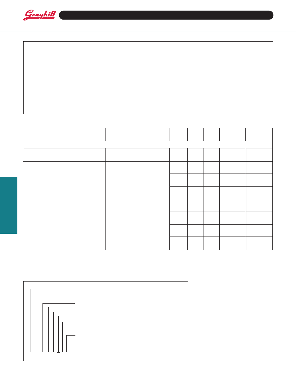
Series
Lock Style: per Choices Chart J4, J8, J9
Switch Style: per Choices Chart A or P
Angle of throw: 36, 45, 60 or 90 (per Choices chart)
Number of Decks: 01
Poles per Deck: = 1 or 2 (per Choices chart)
Positions per Pole: 02 thru 10 (per Choices chart)
type of contacts: (per Choices chart)
N = Non-shorting
S = Shorting
Stop Arrangement Suffix:
(needed only for 1-pole switches with maximum positions)
F = Fixed stop between last and first positions
*Leave blank for continuous rotation
58J8A36-01-1-10N-f
orDeriNg iNforMAtioN
Available from your local grayhill Distribu-
tor. For prices and discounts, contact a local
Sales Office, an authorized local Distributor
or Grayhill.