Keylock rotary switches, Lock specifications, Circuitry – Grayhill Keylock Switches 58 Series User Manual
Page 2: Switch specifications, General characteristics, Electrical characteristics, Materials & finishes
Grayhill, Inc. • 561 Hillgrove Avenue • LaGrange, Illinois 60525-5997 • USA • Phone: 708-354-1040 • Fax: 708-354-2820 • www.grayhill.com
Rotary Switches
Keylock Rotary Switches
Lock SPecificAtioNS
general characteristics
Mounting: By bushing, nut and lockwasher
keying: All locks keyed alike except by
special order
orientation of keylock Switch: Lock flats
on both sides with key upright (cut side
down) in position 1.
key removals:
36° Throw Switch
At every position or
At 0° & 180°
45° Throw Switch
At every position or
At 0°, 90°, 180°, 270°
60° Throw Switch
At every position or
At 0°, 180°
90° Throw Switch
At every position or
At 0°, 180°
Optional pulls
Contact Grayhill
electrical characteristics
Chart is shown for non-shorting contacts and
resistive load and for the life limiting criteria
indicated below. The data for the curve
was measured at sea level, 25°C and 68%
relative humidity. Contact Grayhill for more
information
if any of the following is true: life limiting criteria
are more critical than those listed; more cycles
of operation are required; a larger make
and break current is required; the operating
environment includes elevated temperatures
or reduced pressures.
Curve A: 220 Vac all angles
of throw.
Curve B: 115 Vac and 30
Vdc for all angles of throw.
300
200
0
0
10
20
30
CYCLES x 1000
CURRENT MILLIAMPS
100
A
B
36° Angle of throw
45° Angle of throw
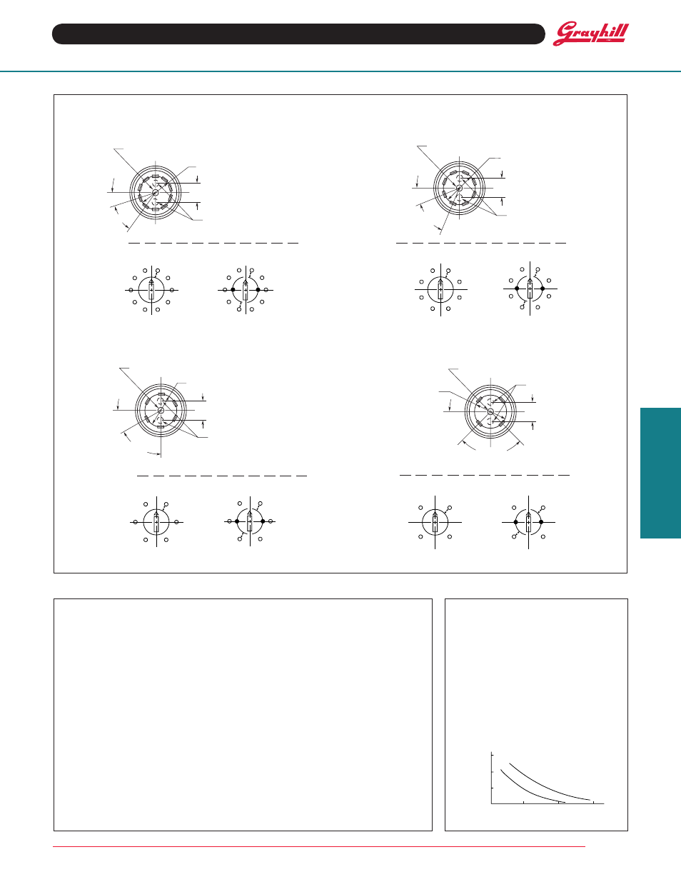
circuitry
90° Angle of throw
VIEWED FROM FRONT END; SHOWN IN POSITION 1.
VIEWED FROM FRONT END; SHOWN IN POSITION 1.
reAr
View
TWO POLE
ONE POLE
ONE POLE
TWO POLE
60° Angle of throw
ONE POLE
TWO POLE
ONE POLE
TWO POLE
VIEWED FROM FRONT END; SHOWN IN POSITION 1.
VIEWED FROM FRONT END; SHOWN IN POSITION 1.
reAr
View
reAr
View
reAr
View
6
7
8
9
10
1
2
3
4
5
C2
C1
6
7
8
9
10
1
2
3
4
5
7
8
1
2
3
4
5
6
7
8
1
2
3
4
5
6
C2
C1
1
2
3
4
5
6
1
2
3
4
5
6
C2
C1
4
1
2
3
4
1
2
3
C2
C1
18˚
36˚
.320
±
.015 (8,13
±
0,38) DIAMETER
CIRCLE OF TERMINAL CENTERS
LOCATION OF COMMONS
2 POLES
COMMON TERMINAL (1 POLE)
POS. 1
.125
±
.015
(3,18
±
0,38)
45˚
22.5˚
.320
±
.015 (8,13
±
0,38) DIAMETER
CIRCLE OF TERMINAL CENTERS
LOCATION OF COMMONS
2 POLES
COMMON TERMINAL (1 POLE)
POS. 1
.125
±
.015
(3,18
±
0,38)
60˚
30˚
LOCATION OF COMMONS
2 POLES
POS. 1
.125
±
.015
(3,18
±
0,38)
COMMON TERMINAL (1 POLE)
.320
±
.015 (8,13
±
0,38) DIAMETER
CIRCLE OF TERMINAL CENTERS
45˚
90˚
LOCATION OF COMMONS
2 POLES
POS. 1
.125
±
.015
(3,18
±
0,38)
COMMON TERMINAL (1 POLE)
.320
±
.015 (8,13
±
0,38)
DIAMETER CIRCLE OF
TERMINAL CENTERS
Materials & finishes
keys: Brass; 2 supplied
Lock Barrel & Plug: Zinc, clear chromate
Lockwasher: Steel, tin zinc plated
Mounting Nut: Steel, nickel-plated
tumbler Plates: Brass
Switch SPecificAtioNS