Verall, Imensions, Eatures – General Machine Products 70483 Hydraulically Limited Cable Puller User Manual
Page 6: Etup of, Uller
H
YDRAULICALLY
L
IMITED
F
IBER
O
PTIC
C
ABLE
P
ULLER
O
PERATION
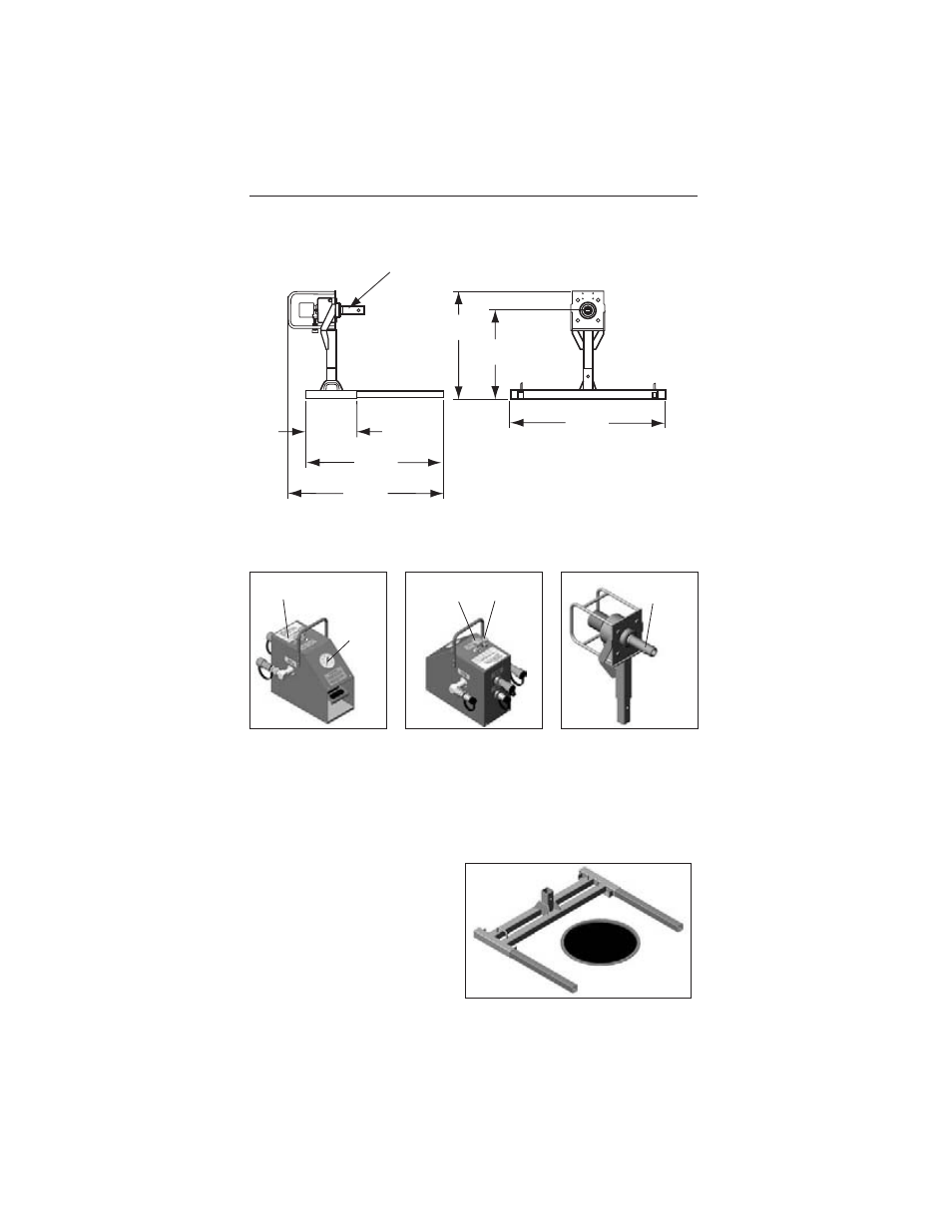
6.0 O
VERALL
D
IMENSIONS
7.0 K
EY
F
EATURES
8.0 S
ETUP OF
P
ULLER
Use caution when lifting hydraulically limited cable puller. Use only proper equip-
ment and manpower. Improper lifting could result in injury or property damage.
1. Place puller stand on ground
over pull box or manhole. Align
the puller stand so the extension
legs will straddle the pull box or
manhole. Install the extension
legs into the ends of the stand.
Verify that extension legs strad-
dle the pull box or manhole as
shown. See fig. 1.
6
Force Calibration Cross
Reference Chart
Pressure
Gauge
Speed
Adjustment
Knob
Force
Adjustment
Knob
Bell Standard
Bayonet Shaft
Foot Control Valve
Hydraulically Limited Fiber Optic
Cable Puller Motor Assembly
[
406.40 mm
]
16.00"
[
1104.90 mm
]
43.50"
49.41"
[
1254.91 mm
]
[
863.30 mm
]
33.99"
[
712.22 mm
]
28.04"
2-7/16" Ø BELL STANDARD
BAYONET SHAFT
[
1421.68 mm
]
55.97"
Figure 1
Foot Control Valve