1 rack mounting, 2 mains voltage, 3 audio connections – Behringer M IC 2200 User Manual
Page 12
12
ULTRAGAIN PRO MIC2200
3.1 Rack mounting
The BEHRINGER ULTRAGAIN PRO fits into one standard 19" rack unit of space (1 3/4"). Please allow at least
an additional 4" depth for the connectors on the back panel. Be sure that there is enough air space around the
unit for cooling and please do not place the ULTRAGAIN PRO on high temperature devices such as power
amplifiers etc. to avoid overheating.
3.2 Mains voltage
Before you connect your ULTRAGAIN PRO to the mains, please make sure that your local voltage
matches the voltage required by the unit! The fuse holder on the female mains connector has 3 triangular
markers, with two of these triangles opposing each other. Your ULTRAGAIN PRO is set to the operating
voltage printed next to these markers, and can be set to another voltage by turning the fuse holder by 180°.
CAUTION: this instruction does not apply to export models exclusively designed, e.g. for 115 V op-
eration!
+
Please refer to the specifications for detailed information about specific voltage supplies!
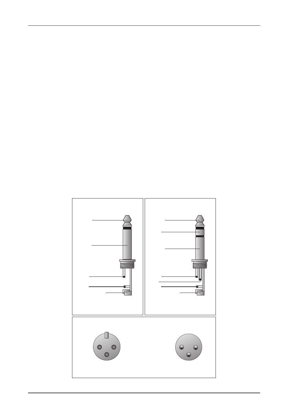
3.3 Audio connections
The audio inputs and outputs on the BEHRINGER ULTRAGAIN PRO are fully balanced. If possible, connect
the unit to other devices in a balanced configuration to allow for maximum interference immunity.
+
Please ensure that only qualified persons install and operate the ULTRAGAIN PRO. During
installation and operation the user must have sufficient electrical contact to earth. Electro-
static charges might affect the operation of the ULTRAGAIN PRO!
Unbalanced use of
mono 1/4" jack plugs
Ring
Balanced use of
stereo 1/4" jack plugs
Balanced use with XLR connectors
1
2
3
2
1
3
Input
Output
Tip =
Signal
Tip =
hot (+ve)
Sleeve =
Ground / Shield
Sleeve =
Ground / Shield
Tip
Tip
Sleeve
Sleeve
Strain relief clamp
Strain relief clamp
Ring =
cold (-ve)
For connection of balanced and
unbalanced plugs, ring and sleeve have
to be bridged at the stereo plug.
1 = Ground / Shield
2 = hot (+ve)
3 = cold (-ve)
For unbalanced use pin 1 and pin 3 have to be bridged
Fig. 3.1: Different plug types
3. INSTALLATION