Safety expansion contact block esm-es3, User information – EUCHNER ESM-ES3xx User Manual
Page 2
2
User Information
EUCHNER GmbH + Co. KG Kohlhammerstraße 16 D-70771 Leinfelden-Echterdingen Tel. +49/711/75 97-0 Fax +49/711/75 33 16 www.euchner.de [email protected]
Safety Expansion Contact Block ESM-ES3..
Note: The items listed under “Electrical connection” must be observed during commissioning.
Commissioning
Procedure
1. Wiring ESM-ES3.. :
Wire the ESM-ES3.. with the EUCHNER basic device
according to your application (see Fig. 1 to Fig. 2).
2. Wiring basic device:
Wire the basic device according to the required Perform-
ance Level determined (see user information for the basic
device).
3. Wiring feedback loop:
Wire the feedback loop as shown in Fig. 3 and Fig. 4.
4. Wiring power supply:
Connect the power supply to terminals A1 and A2 (Fig. 5).
Warning: Wiring only in de-energized state.
5. Starting the device:
Switch the operating voltage on.
Warning:
If the “Automatic start” starting behavior is set on the basic
device, the safety contacts will close immediately.
If the “Monitored manual start” starting behavior is set, close
the start button on the basic device to close the safety
contacts.
The LEDs K1 and K2 on the basic device and on the ESM-
ES3.. are lit.
6. Triggering safety function:
Open the emergency stop circuit by actuating the con-
nected safety switch. The safety contacts of the basic de-
vice and the ESM-ES3.. open immediately.
7. Reactivation:
Close the emergency stop circuit. If “Automatic start” is
selected on the basic device, the safety contacts will close
immediately.
If the “Monitored manual start” starting behavior is set, close
the start button on the basic device to close the safety
contacts of the basic device and the ESM-ES3...
Depending on the application, the device must be wired with a EUCHNER basic device as shown in Fig. 1 to Fig. 2. If the
devices are wired inside a control cabinet (minimum degree of protection IP54), the fault involving a short circuit between the
activation lines can be ruled out (protected wiring space). Category 4, PL e according to EN ISO 13849-1 is thereby possible.
If this fault cannot be ruled out, category 3, PL e is achieved.
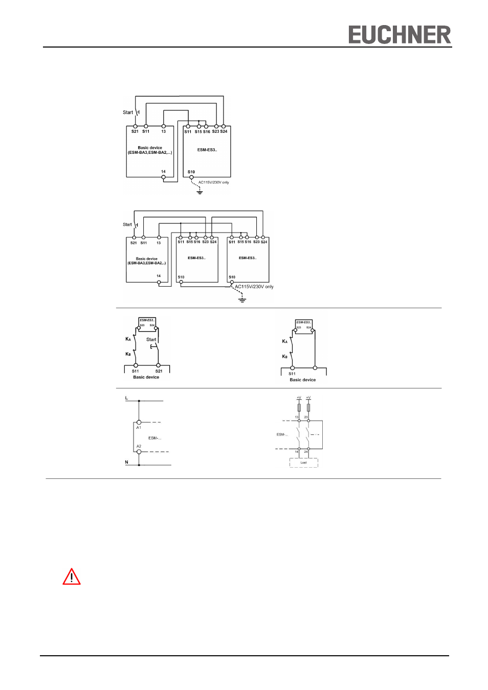
Applications
Fig. 3: Feedback loop
Contactors connected to the ESM-ES3..
or the basic devices are monitored via
the feedback loop of the basic device. K
A
and K
B
are the positively driven contacts
of the connected contactor or expansion
module.
Fig. 2: Connection of several ESM-ES3.. units to
basic device
If further ESM-ES3.. units are to be integrated into the system,
terminals S11 must be connected in parallel on all ESM-ES3..
units. This also applies to terminals S10 and terminals S15/S16.
Fig. 1: Connection of ESM-ES3.. to basic device
Wiring of the ESM-ES3.. via only 4 lines:
A safety contact of the basic devices (e.g. 13-14) activates the
relays of the ESM-ES3.. (S11 and S15/S16).
Two lines on S23 and S24 are required for feedback/fault moni-
toring. A fault in the ESM-ES3.. thereby prevents the entire
safety chain from restarting.
Earth faults in the control lines are detected in addition to inter-
nal faults.
Wiring
Feedback Loop
Notice:
In order to activate earth fault monitoring, S10 must be con-
nected to PE (protective earth) on the AC115/230V devices.
With AC/DC 24 V, connect PE only to the power supply unit
according to EN60204-1.
Fig. 4: Feedback Loop with Auto-Start
Contactors connected to the ESM-ES3.. or the
basic devices are monitored via the feedback
loop of the basic device. K
A
and K
B
are the
positively driven contacts of the connected
contactor or expansion module.
Power supply
and
Safety contacts
Fig. 5:
Power supply A1 and A2.
(Power supply according to techn.
data )
Fig. 6:
Connecting load to safety contacts.
(Figure shows example.
Voltage „+V“ according to techn.
data)
S12