Emergency stop safety relay esm-ba3, User information – EUCHNER ESM-BA3xx User Manual
Page 3
3
User Information
EUCHNER GmbH + Co. KG Kohlhammerstraße 16 D-70771 Leinfelden-Echterdingen Tel. +49/711/75 97-0 Fax +49/711/75 33 16 www.euchner.de [email protected]
Emergency Stop Safety Relay ESM-BA3..
Maintenance
The device must be checked once per month for proper
function and for signs of tampering and bypassing of the
safety function.
Techn. Data
Operating voltage
ESM-BA301 ESM-BA302 ESM-BA303
AC/DC 24V
AC 115V
AC 230V
Rated supply frequency
50-60 Hz
Permissible deviation
+ / - 10%
Power consumption
DC 24V
AC 230V
approx. 2.3 W approx. 6.9 VA
Control voltage at S11
DC 24 V
Control current S11...S14
approx. 60 mA
Safety contacts
3 NO contacts
Auxiliary contacts
1 NC contact
Max. switching voltage
AC 250 V
Safety contact breaking capacity (13-14, 23-24, 33-34)
AC:
250 V, 2000 VA, 8 A for ohmic load,
250 V, 3 A for AC-15
DC: 50 V, 400 W, 8 A for ohmic load;
24 V, 3 A for DC-13
Max. total current through all 3 contacts
15 A (13-14, 23-24, 33-34) *)
Auxiliary contact breaking capacity (41-42)
AC: 250 V, 500 VA, 2 A for AC-12
DC: 50 V, 100 W, 2 A for DC-12
Minimum contact load
24 V, 20 mA
Contact fuses
6 A slow-blow or 8 A quick-action or 10 A gG
Line cross section
0.14 - 2.5 mm
2
Max. length of control line
1000 m with 0.75 mm
2
Contact material
AgNi
Contact service life
mech. approx. 1 x 10
7
, electr. 1 x 10
5
operating cycles
Test voltage
2.5 kV (control voltage/contacts)
Rated impulse withstand voltage, leakage path/air gap
4 kV (DIN VDE 0110-1)
Rated insulation voltage
250 V
Degree of protection
IP20
Temperature range
-15°C to +40°C *)
Degree of contamination
2
(DIN VDE 0110-1)
Overvoltage category
3
(DIN VDE 0110-1)
Weight
approx. 230 g
Mounting
DIN rail according to EN 60715TH35
Safety
Characteristics
According to
EN ISO 13849-1
Note:
Additional data can be requested from the manufacturer for
applications that deviate from these conditions.
The device is certified according to EN ISO 13849-1 up to a
Performance Level of PL e.
Device cannot be switched on again after an emergency
stop:
•
Check whether the emergency stop circuit was closed
again.
•
Was the start button opened before closing of the emer-
gency stop circuit (with manual start)?
•
Is the feedback loop closed?
If the fault still exists, perform the steps listed under
“Commissioning Procedure”.
If these steps do not remedy the fault either, return the
device to the manufacturer for examination.
Opening the device is impermissible and will void the
warranty.
Device does not switch on:
•
Check the wiring by comparing it to the wiring diagrams.
•
Check the safety switch used for correct function and
adjustment.
•
Check whether the emergency stop circuit is closed.
•
Check whether the start button (with manual start) is
closed.
•
Check the operating voltage at A1 and A2.
•
Is the feedback loop closed?
What to Do in
Case of a Fault?
The device is otherwise maintenance free, provided that it
was installed properly.
*) If several ESM-BA3.. devices are closely spaced under load, the max. total current at the ambient temperature of T=20°C: 9A; at T=30°C: 3A; at T=40°C =1A.
If these currents are exceeded, a spacing of 5 mm between the devices must be observed.
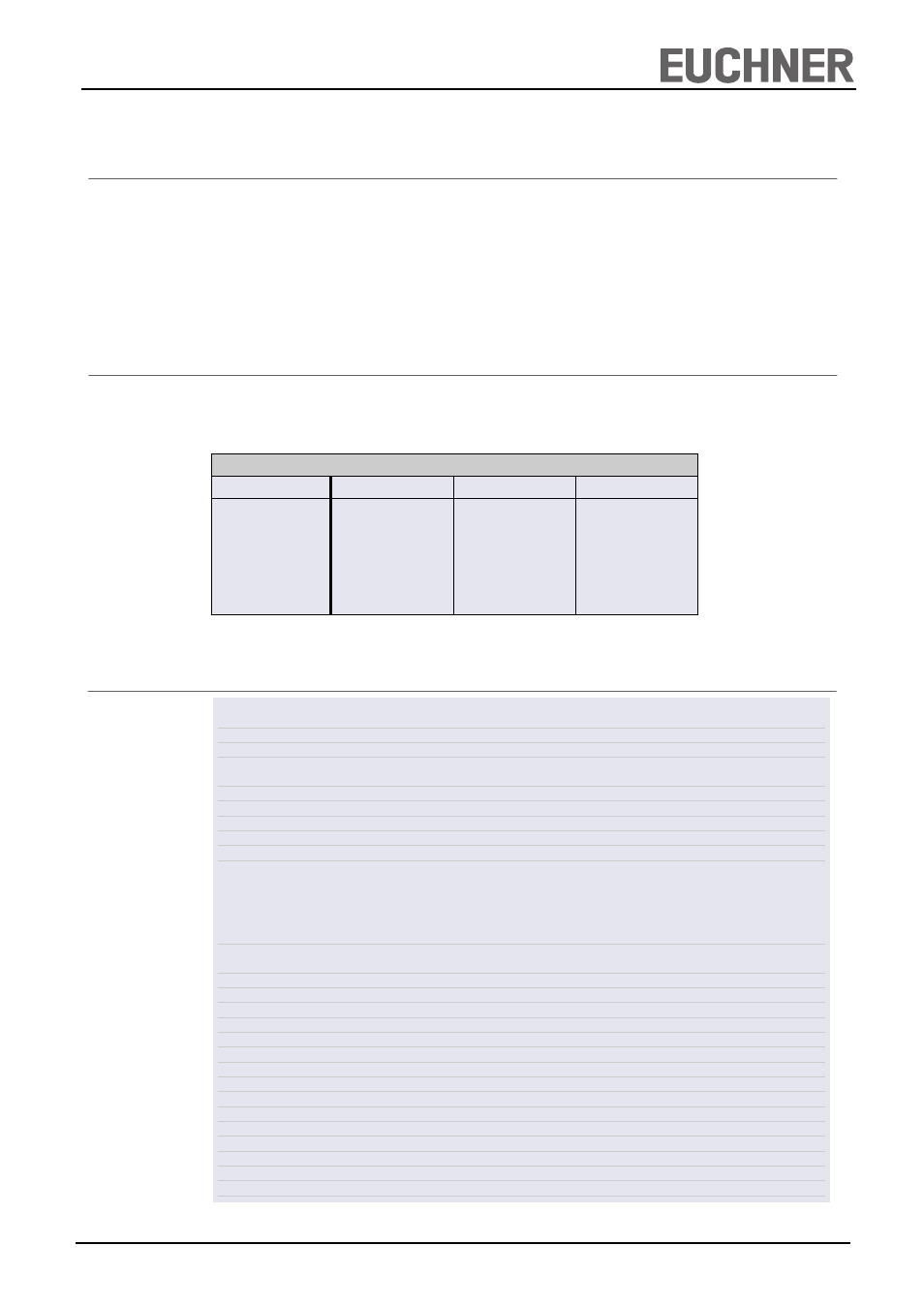
Safety characteristics according to EN ISO 13849-1 for all variants of ESM-BA3
Load (DC-13; 24V)
<= 0,1A
<= 1A
<= 2A
T10d [years]
20
20
20
Category:
4
4
4
PL
e
e
e
PFHd [1/h]:
1,2E-08
1,2E-08
1,2E-08
nop [cycle / year]
<= 500.000
<= 350.000
<= 100.000