Combination options, Technical data, Figure 1: alignment of read head and actuator – EUCHNER CMS(06/12) User Manual
Page 4
Operating Instructions Read Heads/Actuators with Hall Sensors for Evaluation Units CMS
EUCHNER GmbH + Co. KG
Kohlhammerstraße 16
D-70771 Leinfelden-Echterdingen
Tel. +49 711 7597-0
Fax +49 711 753316
www.euchner.de
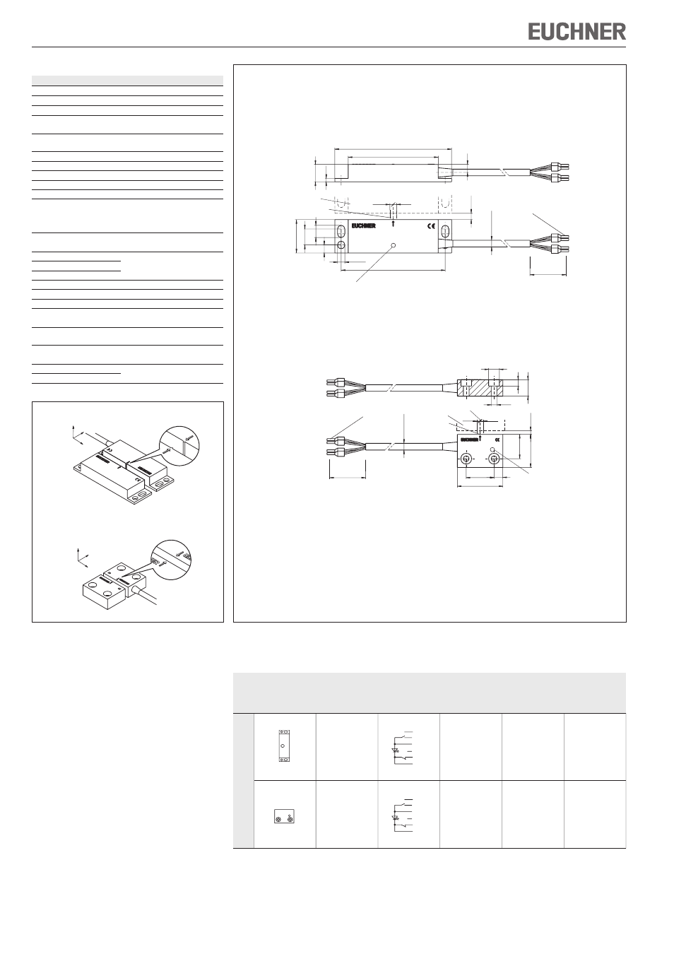
Figure 2: Dimension drawings for read heads CMS-RH-A.. / CMS-RH-B..
Dimension drawings for actuators CMS-MH-A. / CMS-MH-B.
Excluding the connection cable and the
LED, the actuator dimensions are the same
as those of the read head.
CMS-RH-A..
CMS-MH-A.
CMS-RH-B..
CMS-MH-B.
Subject to technical modifications; no r
esponsibility is accepted for the accuracy of this information.
© EUCHNER GmbH + Co. KG
1
13226-01-06/12 (translation of the original operating instructions)
Circuit
Assured
Assured
Read
diagram
switch-on
switch-off
Design
head
not
Actuator
distance
distance
actuated
s
ao
[mm]
1)
s
ar
[mm]
2)
CMS-RH-AYA-...L
BN +
PK
WH
BK
BU -
GY NC
CMS-MH-AA
10
20
CMS-RH-BYB-...L
BN +
PK
WH
BK
BU -
GY NC
CMS-MH-BB
6
13
1)
There must be no ferromagnetic material in the vicinity of the read head or the actuator.
All data refer to the frontal approach direction and a center offset of m = 0.
2)
The assured switch-off distance corresponds to the reset distance.
Combination options
Evaluation units
CMS-E-ER und CMS-E-FR
Technical data
Parameter
Value
Read heads
Housing material
Reinforced PPS
Ambient temperature
-5 ... +55 °C
Degree of protection
acc. to EN 60529
IP 67
Installation position
Any, alignment with actuator should
be kept in mind (markings)
Connection
Molded cable with crimped ferrules
Switching voltage
20 ... 35 V
Current consumption I
max.
35 mA
Switching current I
e
max.
15 mA
Method of operation
Hall sensor
In compliance with
EN 60068-2-2; EN 60947-5-3;
EN 61000-6-2; EN 61000-6-3;
EN 55022; EN 60204-1;
EN ISO 13849-1; EN 1088
Center offset m
± 2.5 mm at a distance
from actuator
of s = 3 mm
Switch-on distance s
ao
See table listing
Switch-off distance s
ar
combination options
Switching contacts
Actuator
Housing material
Reinforced PPS
Ambient temperature
-20 ... +60 °C
Degree of protection
acc. to EN 60529
IP 67
Installation position
Any, alignment with read head
should be kept in mind (markings)
Center offset m
± 2.5 mm at a distance
from read head
of s = 3 mm
Switch-on distance s
ao
See table listing
Switch-off distance s
ar
combination options
Figure 1: Alignment of read head and actuator
X
Y
Z
Alignment
marking
Approach
direction
X
Y
Z
Approach
direction
Alignment
marking
Design CMS-.-A...
Design CMS-.-B...
2,5
2,5
s
ao
78
±0,1
∅ 5,5
9,
5
25
12
6
6
67,5
87,5
2,
5
13
42
ca.
5,
8
∅
6 x 0,25 mm²
Actuator
Active face
Center offset m at s = 3 mm
LED indicator
LED indicator
2,5
2,5
s
ao
19,
2
26,
2
22
7
36
13
5
8,5
4,5
42
ca.
5,
8
∅
6 x 0,25 mm²
Actuator
Active face
Center offset m at s = 3 mm