Setup, Led indicators, Initial setup – EUCHNER CES-AR-C01-CH-SA (Multicode) User Manual
Page 20: Functional check, Setup 20 led indicators
Operating Instructions Safety Switch CES-AR-C01-CH-SA
20
Setup
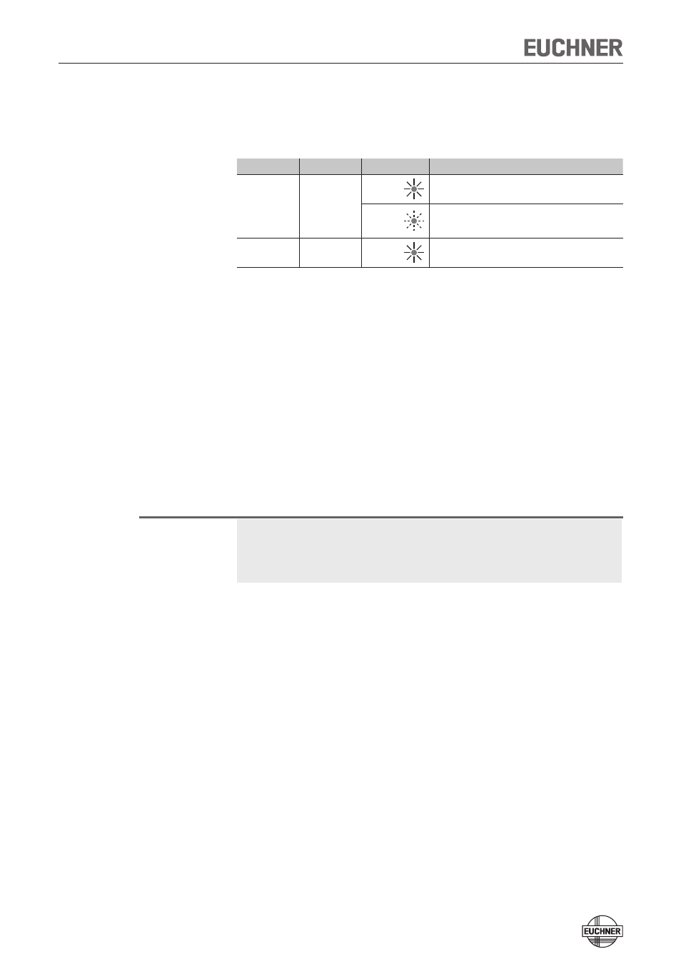
LED indicators
LED
Color
State
Significance
STATE
green
illumi-
nated
Normal operation
flashing
- Teach-in operation or Power Up
- Actuator in limit range (V. 1.1.2 or higher)
(refer to the status table for further signal functions)
DIA
red
illumi-
nated
- Internal electronics fault
- Fault at the inputs/outputs
Initial setup
1. Apply operating voltage to the safety switch.
¨
The green LED flashes quickly (approx. 10 Hz)
A self-test is performed during this time (approx. 8 s). After this, the LED
flashes cyclically one time and signals that it is in standby state.
2. Move actuator to the read head (observe distance < S
ao
).
¨
The green LED illuminates continuously and indicates the detection of the
actuator.
Functional check
After installation and any fault, the safety function must be fully checked. Proceed
as follows:
Warning!
Danger of fatal injury as a result of faults in installation and functional check.
Ì
Before carrying out the functional check, make sure that there are no per-
sons in the danger area.
Ì
Observe the valid accident prevention regulations.
1. Switch on operating voltage.
Ì
The safety switch carries out a self-test.
The green LED STATE flashes for 8 s with 10 Hz.
The STATE LED then flashes at regular intervals.
2. Close all safety guards.
Ì
The machine must not start automatically.
Ì
The green STATE LED illuminates continuously.
3. Enable operation in the control system.
4. Open the safety guard.
Ì
The machine must switch off and it must not be possible to start it as long as
the safety guard is open.
Ì
The green LED STATE flashes at regular intervals.
Repeat steps 2-4 for each safety guard.