Setup, Led indicators, Initial setup – EUCHNER CES-I-AR-M-C04 (Multicode) User Manual
Page 20: Functional check, Setup 20 led indicators
Operating Instructions Safety Switch CES-I-AR-M-C04
20
Setup
LED indicators
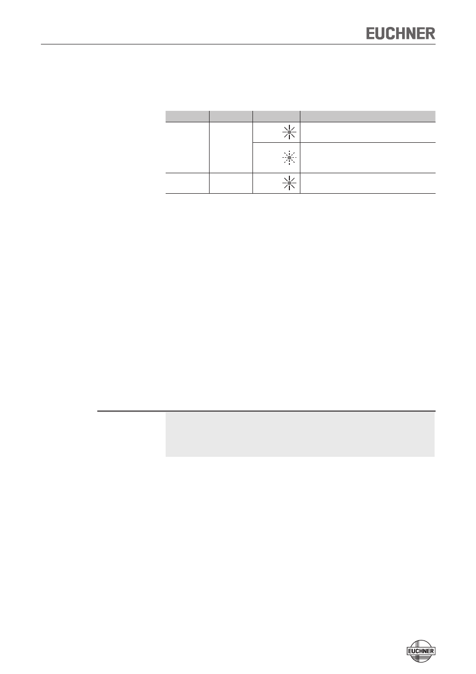
LED
Color
State
Significance
STATE
green
illumi-
nated
Normal operation: Door closed
flashing
- Power Up
- Door open
- Actuator in the limit range
(refer to the status table for further signal functions)
DIA
red
illumi-
nated
- Internal electronics fault
- Fault at the inputs/outputs
Initial setup
1. Apply operating voltage to the safety switch.
¨
The green LED flashes quickly (approx. 5 Hz).
A self-test is performed during this time (8 s). After this, the green LED flash-
es cyclically one time and signals that it is in standby state.
2. Move actuator to the read head (observe distance < S
ao
).
¨
The green LED illuminates continuously and indicates the detection of the
actuator.
If the green LED is flashing quickly, the actuator is in the limit range. In this
case the safety guard must be re-adjusted such that the actuator is com-
pletely in the read area.
Functional check
After installation and any fault, the safety function must be fully checked. Proceed
as follows:
Warning!
Danger of fatal injury as a result of faults in installation and functional check.
Ì
Before carrying out the functional check, make sure that there are no per-
sons in the danger area.
Ì
Observe the valid accident prevention regulations.
1. Switch on operating voltage.
Ì
The safety switch carries out a self-test.
The green STATE LED flashes for 8 s with 5 Hz.
The STATE LED then flashes at regular intervals.
2. Close all safety guards.
Ì
The machine must not start automatically.
Ì
The green STATE LED illuminates continuously.
3. Enable operation in the control system.
4. Open the safety guard.
Ì
The machine must switch off and it must not be possible to start it as long as
the safety guard is open.
Ì
The green STATE LED flashes at regular intervals.
Repeat steps 2-4 for each safety guard.