Caution, Floor level and inboard locator adjustments, Inboard locator adjustment – Braun NUVL603C User Manual
Page 10
Page 8
Floor Level and Inboard Locator Adjustments
Inboard Locator Adjustment
O
P
E
N
C
L
O
S
E
VALVE
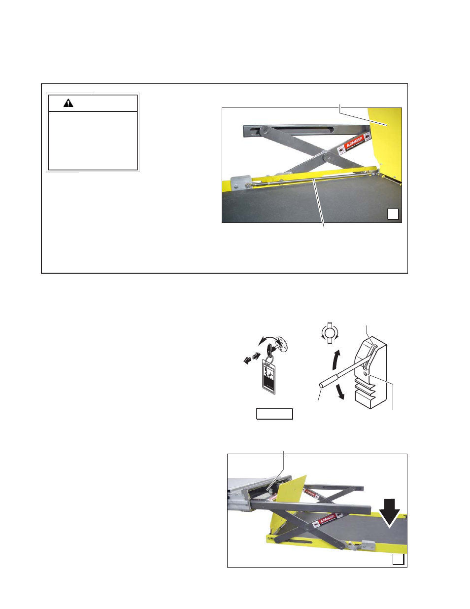
2. Position the lift platform below
stow level using the manual op-
eration system. See Photo C.
Lowering the platform will al-
low access to the cam bolt
securement nut. See Photo E.
CAUTION
Do not adjust in-
board locator link-
age rod. Linkage
rod adjustment may
result in lift damage.
Do not adjust
inboard loca-
tor linkage rod
at this time!
Linkage rod
adjustment is not
required unless
extra usable
platform length
is needed. If
the angle of the inboard locator (when in the
vertical position) restricts the usable platform
length for the wheelchair passenger, adjust-
ment of the linkage rod will change the angle.
With the platform at ground level and the
inboard locator in the vertical position, there
should be a minimum of 1” clearance between
the inboard locator and torque tube.
Adjust the inboard locator as detailed in the
following procedures. Then, adjust the linkage
rod as detailed on page 9 (only if necessary).
Inboard Locator
Linkage Rod
1. Raise the lift platform fully (floor level) us-
ing the manual operation system (Manual
Operating Instructions detailed on Quick
Reference Installation Sheet). If the inboard
locator rests properly on the floor, do not ad-
just the inboard locator. Lower the platform
to ground level. If the angle of the inboard
locator (when in the vertical position), does
not restrict the usable platform length for the
wheelchair passenger, disregard inboard
locator adjustment procedures. See Photo H
on page 9. Refer to the following procedures
if adjustment is required.
Stow Level
Platform
below
Stow
Level
WAR
NIN
G
81823
Push T
-handle in fully
and
manually move platfo
rm in
and out to engage platfo
rm
lock before driving
veh
icle.
Failure to lock platform may
result in unintended platform
deployment. Unintended
platform deployment
may
result in serious bodily injury
and/or property dam
ag
e.
Do not remove!
B
C
Hand
Pump
Valve
Pump
Handle
Figure A
Manual Operation Systems
T-Handle
Release
Cable