Enerpac PTA-Series User Manual
Page 3
3
3.4 Filling Air Lubricator
NOTE:
Oil for the lubricator is provided in the plastic bottle
shipped with the console.
The lubricator may be filled without shutting down equipment,
regardless of whether or not the system is under pressure. To fill
through the fill port, use a bottle with a long spout or a small funnel.
Slowly remove the lubricator fill plug and insert the tip of the bottle
spout or funnel to the bottom of the fill port recess, or oil back-out
will occur. Fill to 1⁄2" below the top of the bowl.
CAUTION: Maintaining the lubricator oil level is
critical to the life of the pump.
3.5 Air Lubricator Adjustment
The adjustment knob (C) is
factory-adjusted so that
when it is turned fully
clockwise, no oil is
delivered to lubricate the
system.
To make initial
adjustment, turn on the air
and start flow to the
system. Turn knob to adjust
oil drip rate. Turning knob
c o u n t e r - c l o c k w i s e
increases drip rate. Set the
drip rate to one or two drops
per minute initially and fine
tune the rate after the
system reaches its normal
operating temperature.
To check lubrication, hold a mirror near the equipment exhaust. If
a heavy film develops, reduce lubrication. Once the final setting
has been determined, remove the knob to prevent tampering with
the adjustment setting.
IMPORTANT:
If the lubricator is used in cycling applications, the
lubricator must stay pressurized during on and off cycles. Cycle
time must be at least 15 seconds, and the flow rate during each
cycle must be at least 4 SCFM.
WARNING: The lubricator has a polycarbonate
bowl. Synthetic base oils or oils containing
phosphate esters or chlorinated hydrocarbons will
attack polycarbonate bowls and can result in a rupture of
the bowl. Do not use an air compressor which uses these
oils. Do not expose the bowl to materials such as carbon
tetrachloride, trichlorethylene, acetone, paint thinner,
cleaning fluids, which will cause the plastic to craze or
rupture. Before using the lubricator, consult Enerpac for
further information if you are not sure if a substance in the
work environment will be harmful.
4.0 OPERATION
IMPORTANT:
When possible, a single user should operate the
torque wrench and pump. This can prevent accidental activation of
the pump while the operator is positioning the wrench.
1.
Check all system fittings and connections to be sure they are
tight and leak free.
2.
Check oil level in reservoir. Oil level should be one inch below
breather opening.
3.
To start the pump, press the green ADVANCE/ON button (D)
on the pendant. The tool will advance as long as the button is
held down.
4.
Release the button to retract
the wrench. The motor will
remain on for 10-30 seconds.
5.
Press the red OFF button (E)
on the pendant to stop the
pump motor. Oil from the
retract line will return to tank.
4.1 Air Removal
When the wrench is first connected
to the pump, air will be trapped in
the components. To ensure smooth
and safe operation, remove air by
cycling wrench several times
without load. Cycle until wrench
advances and retracts without
hesitation.
Check oil level before operation.
4.2 Pressure (Torque) Adjustment
WARNING: Make these adjustments BEFORE putting
torque wrench on nut or bolt head. The pump
pressure setting may be above the pressure needed
to provide the required torque for your application.
Exceeding required torque will cause equipment damage and
may lead to serious personal injury.
REFER TO TORQUE WRENCH INSTRUCTIONS FOR
WRENCH OPERATING PROCEDURE.
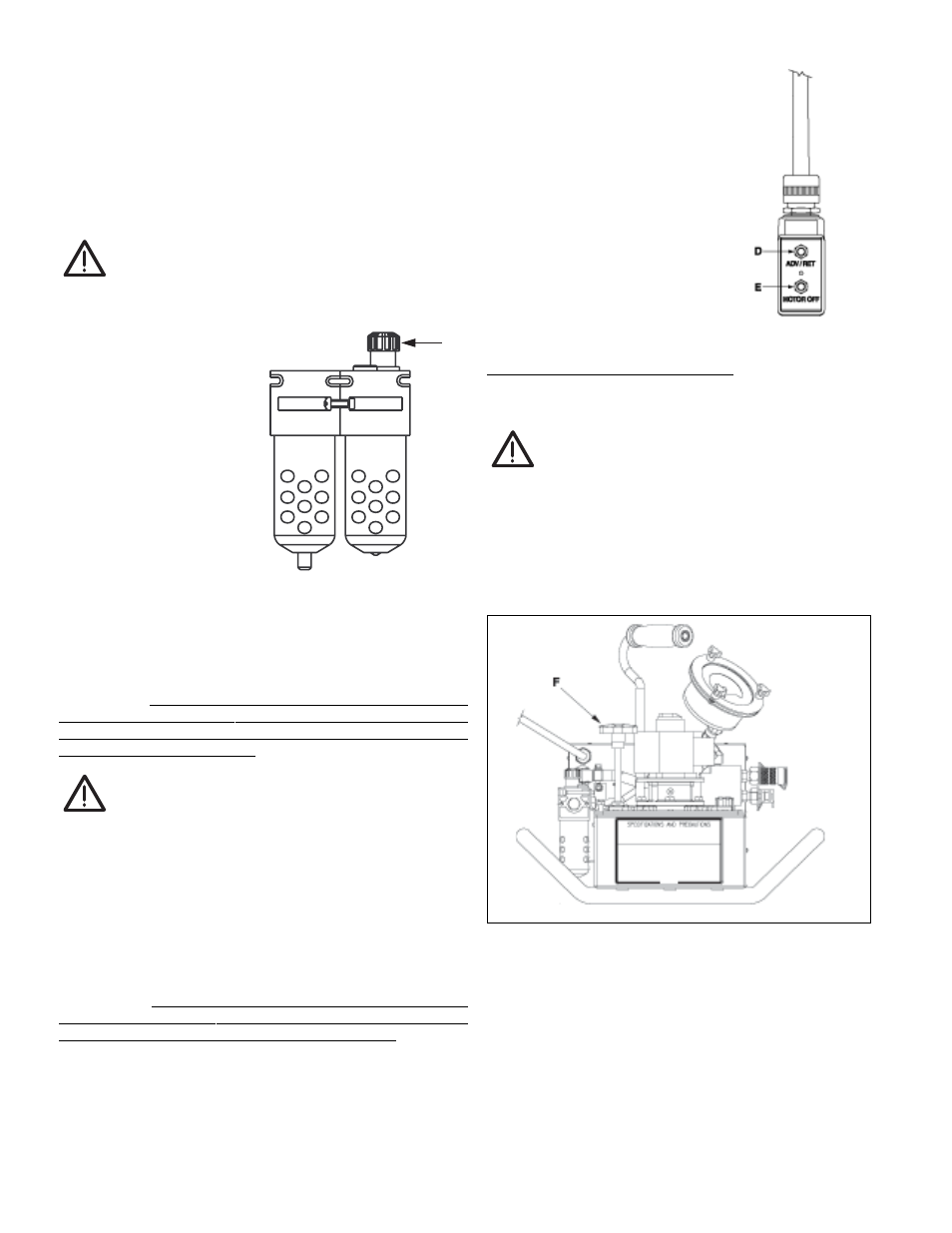
1.
Loosen locknut and back out relief valve (F) to prevent
unintended pressure build-up. (See Figure 5.)
Figure 5
2.
Press and hold the “Advance” pushbutton and read pressure
gauge.
3.
While holding the “Advance” pushbutton, turn relief valve in
(clockwise) to increase pressure or out (counter-clockwise) to
decrease maximum pressure. Repeat until correct pressure is
obtained. NOTE: THE "ADVANCE" button must be released
and then repressed to verify pressure when decreasing
pressure setting.
4.
Tighten locknut on relief valve to maintain setting.
5.
Run the pump several times to test the pressure setting.
C
Figure 3
Figure 4