Open, Closed, Close open – Enerpac ZUTP-Series User Manual
Page 3
3
4.0 INSTALLATION
Install or position the pump to ensure that air fl ow around the
motor and pump is unobstructed. Keep the motor clean to
ensure maximum cooling during operation.
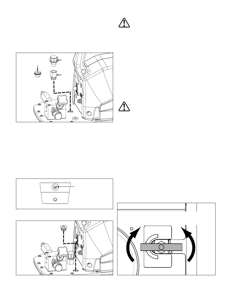
4.1 Air Breather (See Figure 1)
A shipping plug (A) is installed in the breather port on the top of
the reservoir. Before using the pump, replace the shipping plug
(A) with the air breather (B) and adapter fi tting (C).
A
C
B
Figure 1, Air Breather
4.2 Oil Level (See Figures 2 and 3)
Check the pump oil level prior to start-up. The reservoir is full
when the oil level is as shown in Figure 2. If necessary, remove
the oil fi ll plug from the cover plate as shown in Figure 3 and add
oil as required.
IMPORTANT: Add oil only when all system components are fully
retracted, or the system will contain more oil than the reservoir
can hold. Reservoir capacity is approximately 1 gallon [3,8 liters].
Tank is full
when oil level
is here.
Figure 2, Oil Level Sight Glass
Figure 3, Oil Fill Plug
4.3 Electrical Connections
WARNING: The pump is factory equipped with the
common electrical plug for a given voltage. Altering the
plug type should only be done by a qualifi ed electrician,
adhering to all applicable local and national codes.
• The disconnect and line circuit protection is to be provided by
customer. Line circuit protection is to be 115 percent of motor full
load current at maximum pressure of application.
• For additional information, refer to power rating on pump name
plate. Also refer to graph in Section 3.1.
4.4 Hydraulic Connections
• A female quick-disconnect fi tting (Enerpac Model BR150) is
installed at the pump oil outlet. This fi tting is rated at 21,750 psi
[1500 bar].
• Enerpac recommends the use of Enerpac HT 1500 Series
thermoplastic hoses with the Model ZUTP-1500 pump. These
hoses are rated at 21,750 psi [1500 bar]. Refer to Enerpac
instruction sheet L2733 for use, safety and maintenance
information.
WARNING: The Model ZUTP-1500 pump must be
operated only with hoses and fi ttings rated to operate
at 21,750 psi [1500 bar] working pressure. Hydraulic
hoses and fi ttings of a lower pressure rating will rupture or burst.
Serious personal injury could result!
• Before connecting hose to pump oil outlet, check that pump
pressure gauge indicates zero (0) psi/bar. If any pressure is
indicated, fully open the pressure release valve to relieve
pressure. See Section 5.1.
5.0 OPERATION
5.1 Pressure Release Valve (See Figure 4)
Valve Positions:
1. CLOSED - Flow directed to pump hydraulic outlet port.
Pressure builds when pump motor is turned on. Pump holds
pressure when motor is turned off.
2. OPEN - Pressure released to pump hydraulic reservoir.
Pressure will not build when motor is turned on.
IMPORTANT: Close the pressure release valve using hand force
only. Overtightening and/or use of tools may result in damage to
the valve and/or valve seat.
PRESSURE RELEASE VALVE
OPEN SLOWLY
DO NOT CLOSE
USING EXCESSIVE FORCE
CLOSE
OPEN
OPEN
(pressure release
to reservoir)
CLOSED
(oil fl ow to tool)
Figure 4, Pressure Release Valve