Main feedback – ElmoMC SimplIQ Digital Servo Drives-Whi-Solo Installation Guide User Manual
Page 23
Solo Whistle Installation Guide
Installation
MAN-SOLWHIIG (Ver. 1.503)
23
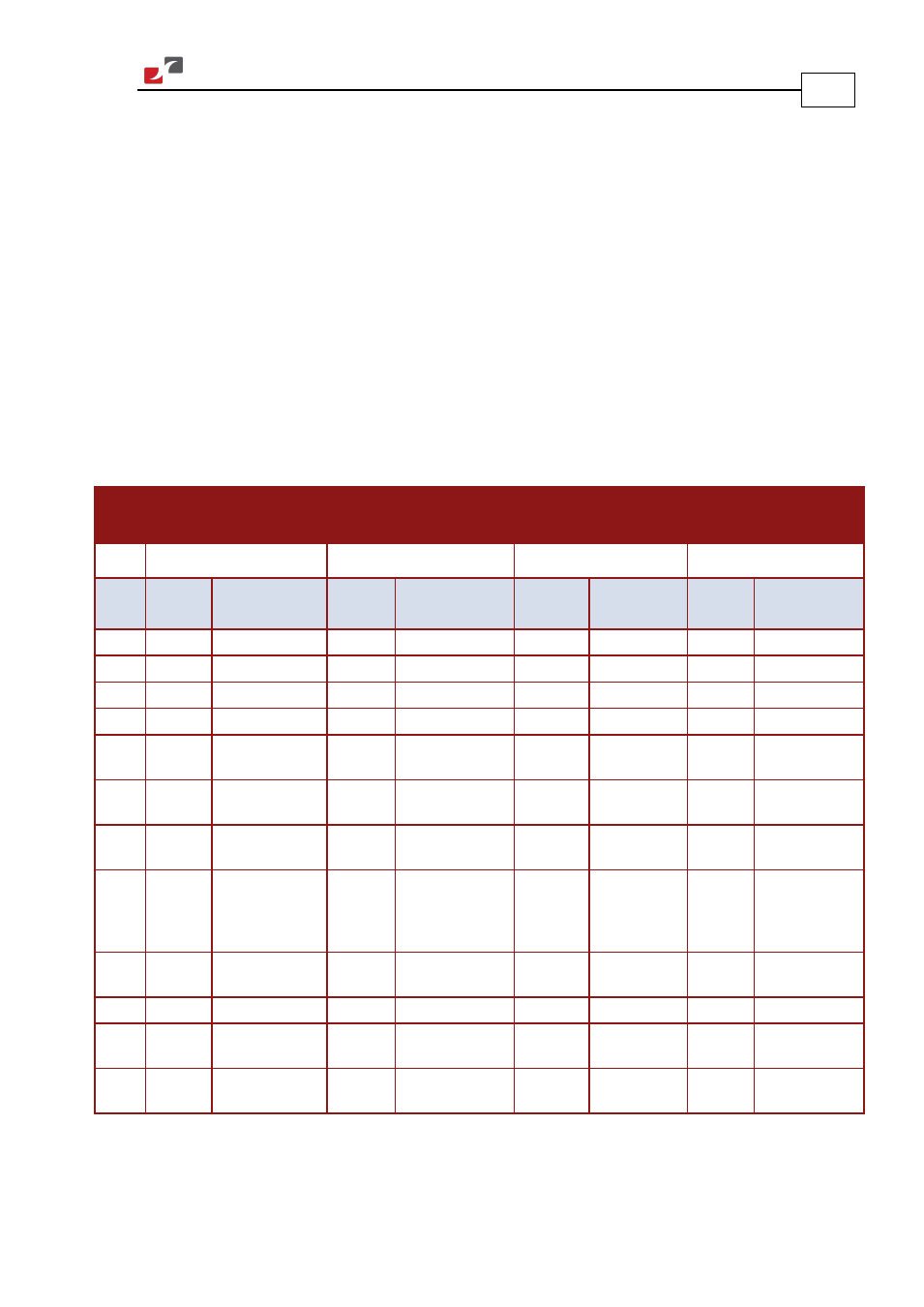
3.6. Main Feedback
The Main Feedback port is used to transfer feedback data from the motor to the drive. In order
to copy the setup to other drives, the phase order on all copy drives must be the same.
The Solo Whistle can accept any one of the following devices as a main feedback mechanism:
•
Incremental encoder only
•
Incremental encoder with digital Hall sensors
•
Digital Hall sensors only
•
Incremental Analog (Sine/Cosine) encoder (option)
•
Resolver (option)
•
Tachometer (option)
•
Potentiometer (option)
Incremental
Encoder
Interpolated Analog
Encoder
Resolver
Tachometer and
Potentiometer
SOL-WHIA
XX
/
YYY
E
ZZ
SOL-WHIA
XX
/
YYY
I
ZZ
SOL-WHIA
XX
/
YYY
R
ZZ
SOL-WHIA
XX
/
YYY
T
ZZ
Pin
(J4)
Signal Function
Signal Function
Signal
Function
Signal Function
1
HC
Hall sensor C input HC
Hall sensor C input NC
-
HC
Hall sensor C input
3
HA
Hall sensor A input HA
Hall sensor A input NC
-
HA
Hall sensor A input
4
PE
Protective Earth
PE
Protective Earth
PE
Protective Earth PE
Protective Earth
5
SUPRET
Supply return
SUPRET
Supply return
SUPRET
Supply return
SUPRET
Supply return
6
+5V
Encoder/Hall +5V
supply
+5V
Encoder/Hall +5V
supply
+5V
Encoder/Hall
+5V supply
+5V
Encoder/Hall +5V
supply
11
CHA-
Channel A
complement
A-
Sine A complement S3
Sine A
complement
Tac 1-
Tacho Input 1 Neg.
(20 V max)
12
CHA
Channel A
A+
Sine A
S1
Sine A
Tac 1+
Tacho Input 1 Pos.
(20 V max)
7
INDEX-
Index complement R-
Reference
complement
R2
Vref
complement
f= 1/TS, 50 mA
Maximum
NC
-
8
INDEX
Index
R+
Reference
R1
Vref f=1/TS,
50 mA Max.
POT
Potentiometer
Input (5 V Max)
2
HB
Hall sensor B input HB
Hall sensor B input NC
-
HB
Hall sensor B input
9
CHB-
Channel B
complement
B-
Cosine B
complement
S4
Cosine B
complement
Tac 2-
Tacho Input 2 Neg.
(50 V max)
10
CHB
Channel B
B+
Cosine B
S2
Cosine B
Tac 2+
Tacho Input 2 Pos.
(50 V max)
Table 2: Main Feedback Pin Assignments