Main and auxiliary power, Main power – ElmoMC Gold Line Digital Servo Drives-Gold Whistle User Manual
Page 36
Gold Whistle Installation Guide
Installation
MAN-G-WHIIG (Ver. 1.208)
36
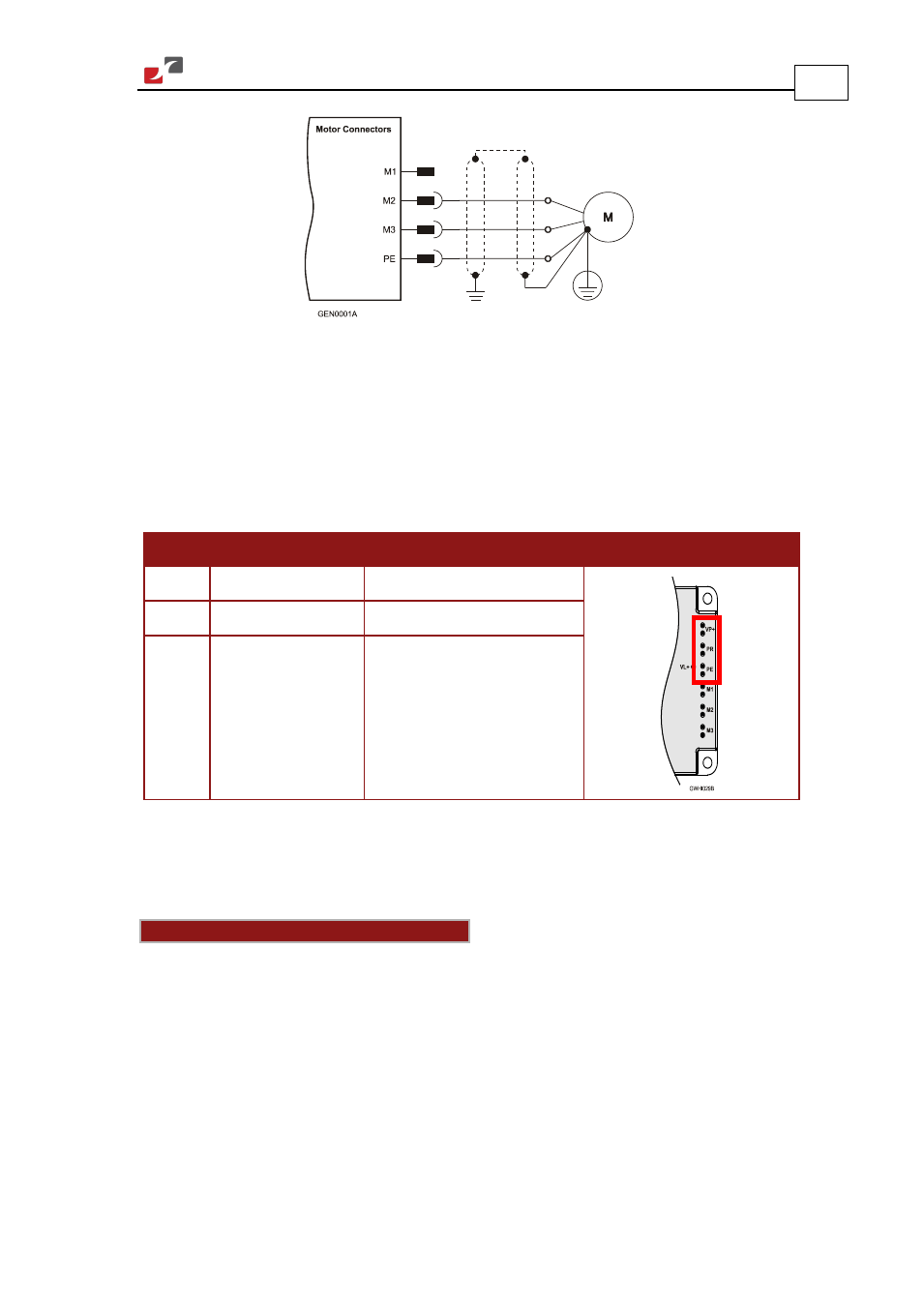
Figure 6: DC Brushed Motor Power Connection Diagram
4.7.2.
Main and Auxiliary Power
This section describes the Main and Auxiliary Power for power ratings 200V and 100V, and
provides details for the optional Backup (Auxiliary) Supply.
4.7.2.1.
Main Power
Pin
Function
Cable
Pin Positions
VP+
Pos. Power input
Power
PR
Power return
Power
PE
Protective earth
Power
Table 10: Connector for Main Power
Power to the Gold Whistle is provided by a 12 to 195 VDC source.
Connect the DC power cable to the VP+ and PR terminals on the Main Power Connector.
Notes for connecting the DC power supply
•
The source of the 12 to 195 VDC power supply must be isolated.
•
For best immunity, it is highly recommended to use twisted and shielded cables for the DC
power supply. A 3-wire shielded cable should be used. The gauge is determined by the
actual current consumption of the motor.
•
Connect the cable shield to the closest ground connection near the power supply.
•
Connect the PE to the closest ground connection near the power supply.
•
Connect the PR to the closest ground connection near the power supply.
•
Before applying power, first verify the polarity of the connection.