Elkhart Brass Universal Seal Replacement Kit For Elkhart Brass and Akron Brass Apparatus Valves User Manual
Page 2
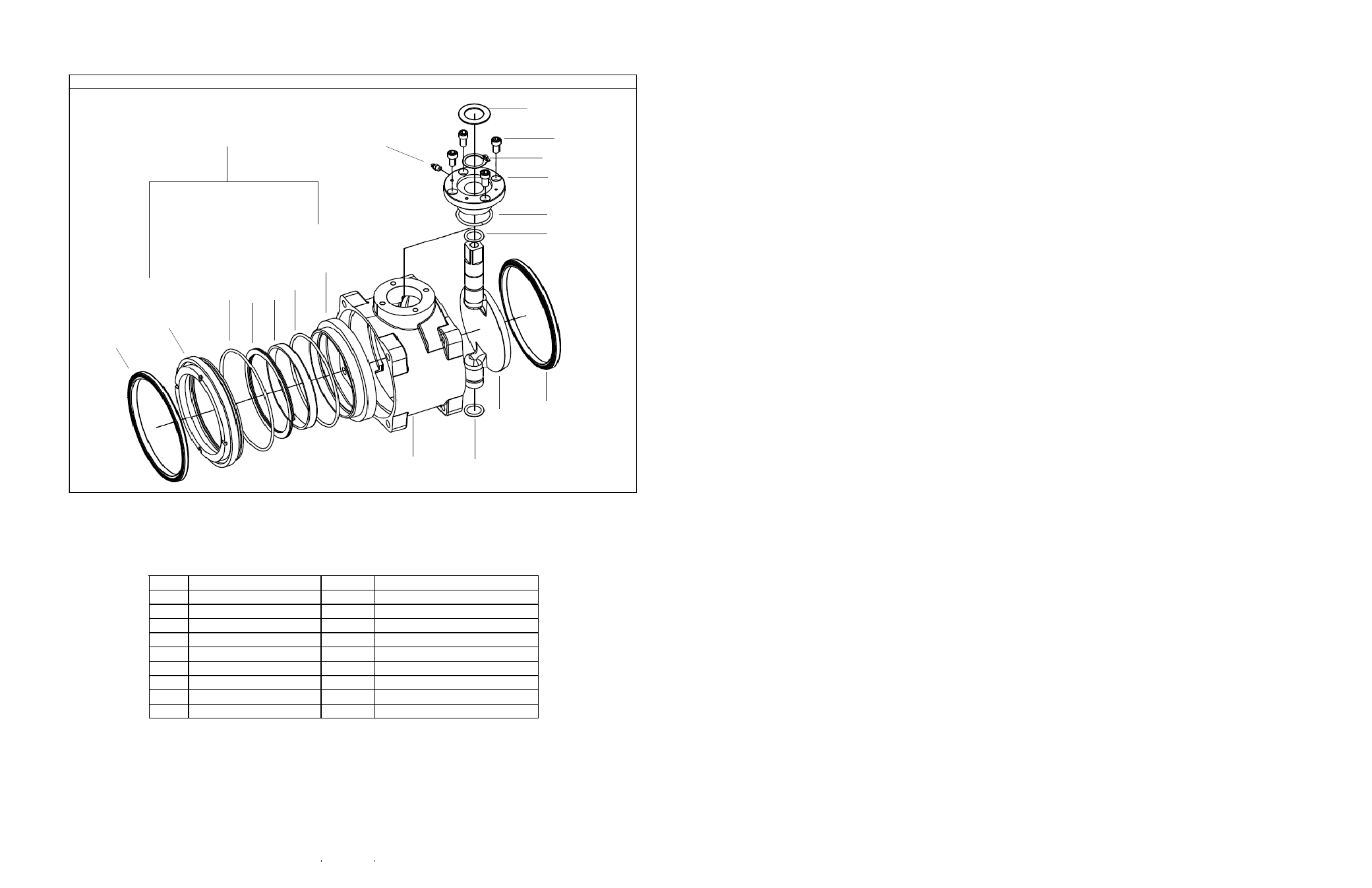
4” Valve Detail – Akron and Elkhart
2.
Inspect the condition of the flat ball for burrs, nicks and sharp edges caused by debris. If found, carefully use fine
emory paper to remove any condition which might cut the valve seat or otherwise impair sealing.
CAUTION: Completely remove any grit or debris from the valve body before assembly.
III.
REASSEMBLY
NOTE: Lubricate O-rings with Parker O-Ring Lube or equivalent petroleum-based lubricant.
1.
Install the new inner O-ring (6) and outer O-ring (3) on the retaining ring (2).
2.
Reinsert the seat spring (4) into the cavity of the retaining ring (2).
3.
Insert the seat support ring (5) into the new seat (7) with the chamfered edge to the inside of the seat.
4.
Insert seat into the seat retaining ring (2).
5.
Replace the entire assembly (18) into the valve body.
6.
Insert the two new adapter seals (1) into the valve body.
7.
Slide valve back into waterway.
NOTE: 4” valves are directional. Note the orientation of the arrow on the side of the valve body indicating flow
direction.
CAUTION: The ball must be in the open positon before the adapter bolts are tightened.
8.
Tighten the adapter bolts evenly in an X pattern using 60-70 ft-lbs torque. DO NOT OVERTIGHTEN.
MAINTENANCE INSTRUCTIONS
Do not lubricate the ball or seats. Lubricants can collect dirt and grit which may cause excessive wear.
Occasionally, flow water through all valves to clear dirt and debris.
OPERATING INSTRUCTIONS
Always open and close valves slowly.
I.
DISASSEMBLY
1.
Turn the valve to the closed position.
2.
If the valve can be rotated out of line, remove three pairs of adapter bolts and loosen the fourth pair. Swing the valve out of
the line. If the valve cannot be rotated out of line, remove all eight adapter bolts and take the valve out completely.
NOTE: 4” Valves are directional. Note the orientation of the arrow on the side of the valve body indicating flow direction.
3.
Remove and discard both adapter seals (1).
4.
Partially open the valve to allow access to the seat assembly (18).
5.
Pull the entire seat assembly (18) out from the valve body.
6.
Discard the seat (7), retaining ring inner O-ring(6) and retaining ring outer O-ring (3).
II.
INSPECTION AND CLEAN-UP
1.
Use a 10” or larger flat file to clean up the flat surface of the adapters and mating surfaces of the valve body. Remove
any paint, corrosion or raised lip around the bolt holes.
DISCLAIMER: Any reference herein to other manufacturers’ names and/or their trademarks is used only for comparison
purposes or to indicate compatibility and is not in any way intended to indicate an association or affiliation with or sponsorship or approval
by that manufacturer.
Do not exceed 500 psi.
ITEM
DESCRIPTION
ITEM
DESCRIPTION
1
Adapter Seal
10
Flat Ball
2
Retaining Ring
11
O-Ring
3
O-Ring
12
O-Ring
4
Seat Spring
13
Gear Case Adapter
5
Support Ring
14
Grease Fitting
6
O-Ring
15
Retaining Ring
7
Seat
16
1/4 - 20 x 5/8 SHCS (4)
8
Body
17
Actuator Washer
9
O-Ring
18
Seat Assembly
18
8
2
1
3
4
6
7
14
17
16
15
13
12
11
1
10
9
5