Warning – Elkhart Brass SPIT-FIRE 08394053 Monitor User Manual
Page 6
6
INSTALLATION INSTRUCTIONS
Monitor Installation
1. Attach companion flange to water supply pipe so that the bolt pattern will allow the monitor to be
installed with the “straight ahead/neutral” position (see Dimensional Drawing section) properly
aligned. Alignment is correct when the “straight ahead/neutral” direction is centered between
adjacent flange bolt holes.
2. Install the monitor assembly on the water supply flange so that it matches up to a 4”-150# flat
faced ANSI flange on the inlet of the monitor, with a flange gasket between the flanges. Install
motor cable junction box by aligning the two-holed bracket with the flange mounting holes on the
rear of the monitor. Secure the inlet flange with eight (8) 5/8”-11 UNC Grade 5 hex head bolts.
Torque bolts to 60-70 ft-lbs.
3. Standpipe must be structurally strong enough to withstand reaction forces of the nozzle when
discharging a straight stream at 90° of the standpipe tower. The formula for calculating nozzle
reaction is: [REACTION FORCE = 0.0505 x GPM x √
PSI]
4. The inlet pressure at the base of the monitor must be high enough to allow for pressure loss
through the monitor. To accomplish this, use the pressure loss for GPM flowing and add to nozzle
pressure. See Monitor Hydraulic Data section for pressure loss chart.
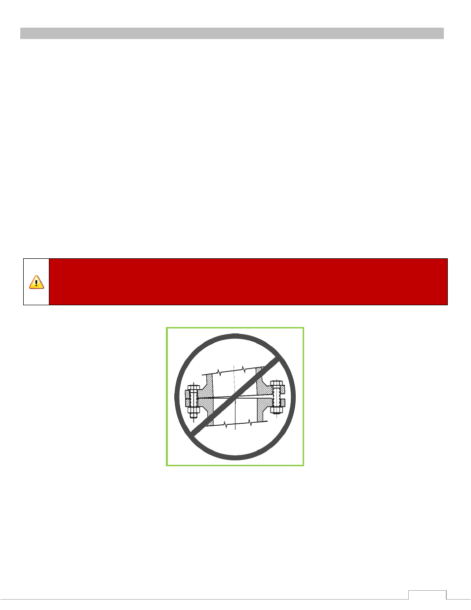
Warning:
When installing the monitor on a raised face companion flange or wafer
type valve, it is critical that the bolts be tightened uniformly to prevent misalignment of
the monitor relative to the flange or valve. If the monitor becomes misaligned, the base
flange will fracture and fail when the bolts on the “high” side are tightened.