Typical pumper truck install guide – Elkhart Brass Sidewinder Typical Pumper Truck Install Guide User Manual
Page 2
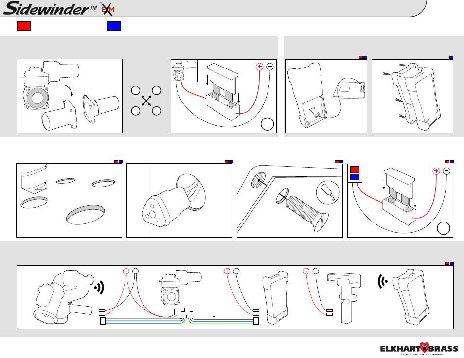
Typical Pumper Truck Install Guide:
Control Components & Accessories
2
4.
5.
6.
A. Follow mounting templates on page
30 of the instruction manual for hole
diameters and dimensions.
B. Drill holes for CAN network and
power cables for each components’
leads behind each component.
C. Mount components to panel using
10-24 x 1/2” screws. Use Loctite 242 or
equivalent.
D. Add a 1A (12VDC)* fuse between
red component lead and positive power
lead.
A. Connect entire CAN network together using 18-22 AWG. Ensure every component connected to the CAN network is connected in between 2 end components that
have CAN termination. Please refer to the BLUE, GREEN, and BLACK lines as the CAN wires below.
*.5A (24VDC)
A. Install valve into plumbing. Torque
adapter bolts to spec using torque specs
to the right
.
7/32” dia.
unless noted
CAN
Network
Wires
18g
98326020 Rev. Rel
1
3
4
2
Tighten Adapter
Bolts using a
cross pattern
25-30 ft-lbs
B. Add a 30A(12VDC)* fuse between
RED controller lead and positive power
lead. *15A(24VDC)
16g
- Panel Mount Controller
Handheld Controller / Docking Station
-
Before continuing please follow the steps on page 14 of the Sidewinder EXM instruction manual outlining the
Monitor Configuration Tool.
Connect power and attach
battery pack to Handheld
controller.
RF Installation - The RF
Module will be upside down
when installed correctly.