Bunn DV User Manual
Page 17
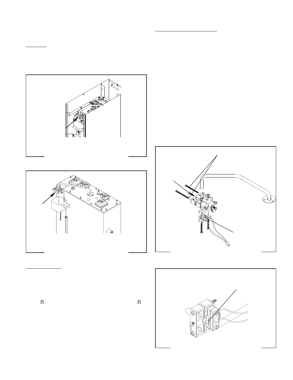
Steam Sensor (Thermistor)
Location:
The thermistor is located on the end of the overfl ow
tube above the overfl ow cup.
To test the thermistor, access will also be needed to
the electronic control board.
SERVICE (cont.)
P1993
FIG. 17b LOCATION
H 10X
P1993
FIG. 17a LOCATION
H 5X
Test Procedure:
1. Disconnect the dispenser from the power source.
2. Disconnect the thermistor from J5 on control
board.
3. Check the resistance across thermistor with a
ohmmeter. The resistance range is approximately
9K @ room temperature to approximately 2K @
200°F.
4. Disconnect the dispenser from the power source.
If resistance was present as described, the thermistor
is working.
If resistance was not present as described, replace the
control board.
Removal and Replacement:
1. Disconnect the dispenser from the power source.
2. Disconnect the thermistor from J5 on control
board.
3. Loosen the set screw and the two screws securing
the two half blocks together. Remove thermistor
assembly from overfl ow tube.
4. Install new thermistor on tube and slide down until
it contacts the fl ared end. NOTE: It’s critical that
the thermistor be centered directly under the tube
opening.
5. Snug the set screw so the block assembly does not
move aroung easily.
6. Connect the thermistor to J5 on control board.
NOTE: DO NOT TEST OPERATION WITH PANELS
REMOVED, AS AIR MOVEMENT CAN HINDER
PROPER READINGS ON THERMISTOR.
Thermistor centered
under tube opening
FIG. 17d THERMISTOR POSITION
42311 080510
Set screw
Mounting screws
DO NOT BEND
THERMISTOR
UP/DOWN
FIG. 17c STEAM SENSOR EXPLODED
17