Bunn DV User Manual
Page 10
10
Electronic Controls (cont.)
7. Reconnect the pink wire to terminal 5 of the elec-
tronic control assembly.
8. Loosen the compression fi tting, remove the probe
from the tank lid, and inspect it for mineral depos-
its. Replace it if necessary. Keep the exposed ends
of the probe away from any metal surface of the
dispenser.
9. Check the voltage across terminals 1 & 4 of the elec-
tronic control assembly with a voltmeter. Connect
the dispenser to the power source. The indication
must be:
a.) 100 to 120 volts ac for 100 to 120 volt models
or
b.) 200 to 240 volts ac for 200 to 240 volt models
or
c.) 230 volts ac for 230 volt models after a delay
of approximately 5 seconds.
10. Touch the screw head end of the probe to the dis-
penser housing. The indication must be 0.
11. Move the probe away from the dispenser housing.
The indication must again be:
a.) 100 to 120 volts ac for 100 to 120 volt models
or
b.) 200 to 240 volts ac for 200 to 240 volt models
or
c.) 230 volts ac for 230 volt models
after a delay of approximately 5 seconds.
12. Disconnect the dispenser from the power source.
Temperature Control Flow Charts (cont.)
If voltage was present as described, reinstall the probe,
the sensing function of the system is operating properly.
If voltage was not present as described, check the pink
probe wire and the green ground wire for continuity
and/or replace the probe.
Temperature Control Test Procedure
1. Disconnect the dispenser from the power source.
2. Check the voltage across terminals 3 & 4 of the
electronic control circuit board with a voltmeter.
Connect the dispenser to the power source.The
indication must be:
a.) 100 to 120 volts ac for 100 to 120 volt models
or
b.) 200 to 240 volts ac for 200 to 240 volt models
or
c.) 230 volts ac for 230 volt models.
3. Disconnect the dispenser from the power source.
4. Check the voltage across the tank heater terminals
with a voltmeter. Connect the dispenser to the
power source. The indication must be:
a.) 100 to 120 volts ac for 100 to 120 volt models
or
b.) 200 to 240 volts ac for 200 to 240 volt models
or
c.) 230 volts ac for 230 volt models.
5. Disconnect the dispenser from the power source.
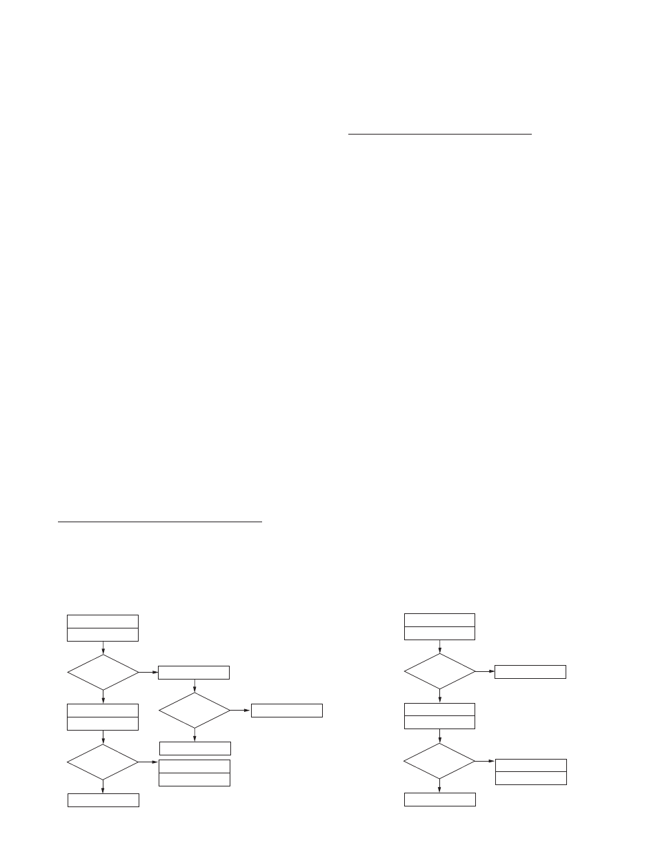
Still Boiling
?
Red Light On While
Boiling
?
Retry
Drain cup
Retry
Disconnect Blue Wire From
Control Board Pin 7
No
Yes
Yes
Yes
No
No
H5X THERMOSTAT
PROBLEM: Boils Excessively - Fills Cup
Still Boiling
?
Replace Steam Sensor
Replace Triac Assembly
Check For Split
Tank Heater
Replace Control Board
Finished
Replace Control Assembly
Still Boiling
?
Red Light On While
Boiling
?
Retry
Drain cup
Retry
Disconnect Blue Wire From
Control Board Pin 7
No
Yes
Yes
No
H5E THERMOSTAT
PROBLEM: Boils
Replace Triac Assembly
Check For Split
Tank Heater
Replace Control Board
Replace Control Assembly
42311 071310