Bunn DV User Manual
Page 11
11
SERVICE (cont.)
Electronic Controls (cont.)
If voltage was present as described, the temperature
control of the system is operating properly.
If voltage was not present as described, contact
Bunn-O-Matic to order an electronic control board and
temperature sensor for evaluation and proceed to #9.
6. Replace the electronic control board.
7. Check the voltage across the tank heater terminals
with a voltmeter. Connect the dispenser to the
power source. The indication must be:
a.) 100 to 120 volts ac for 100 to 120 volt models
or
b.) 200 to 240 volts ac for 200 to 240 volt models
or
c.) 230 volts ac for 230 volt models
8. Disconnect the dispenser from the power source.
If voltage was present as described, the temperature
control of the system is operating properly. Return the
new electronic control board or temperature sensor to
Bunn-O-Matic for credit.
Electronic Controls Removal and Replacement
1. Remove all wires from the electronic control board
terminals.
2. Remove the six 6-32 screws holding the electronic
control board to the component bracket.
3. Disconnect the temperature sensor, overfl ow tube
temperature sensor, and indicator wires from the
electronic control board.
4. Attach the temperature sensor, overflow tube
temperature sensor, and indicator wires to the
electronic control assembly.
5. Fasten the new electronic control board to its
bracket.
6. Refer to Fig 2 when reconnecting the wires.
7. Review the initial set-up procedures on page 6.
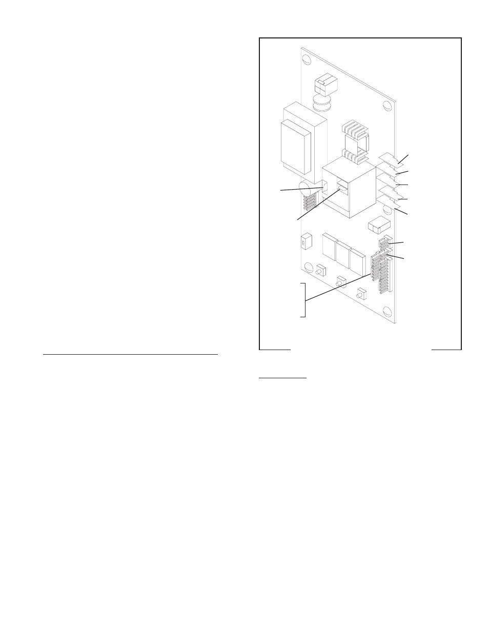
FIG. 11a WIRING CONNECTIONS
Adjustments
The H5X/H10X dispensers hold the water tempera-
ture at the threshold of boiling. It is not adjustable by
the user.
The H5E dispenser is factory calibrated for the
temperature specifi ed on the data plate. If adjustment
is required, use the following procedure:
1. Fill the dispenser according to the steps in the Initial
Set-up.
2. Take the temperature of the stream of water im-
mediately below the faucet as it fl ows from the
dispenser with an accurate thermometer. Do not
take the temperature of water collected in a con-
tainer.
3. If any adjustment is required, refer to LEVEL 1
PROGRAMMING in the Operating Manual.
J3 PNK & GRY to
Heater Indicator
Refi ll Indicator
Power Indicator
Ready Indicator
T5 PNK to Liquid
Level Probe
T4 WHI or RED to
Terminal Block
T3 BLK to Overfl ow
Safety Switch
T2 GRN or GRN/YEL
to Chassis Ground
T1 WHI/BLU to
Solenoid
J4 BLK & WHI to
Temperature Sensor
J5 GRY & GRY toTherm-
istor (H5X only)
BLU to Tank
Heater
WHI/VIO to
Terminal Block
42311 071310