Behringer MDX1400 User Manual
Page 9
9
AUTOCOM PRO MDX1400
2.2 Compressor Section
11
14
16
17
13
10
8
9
7
6
15
5
12
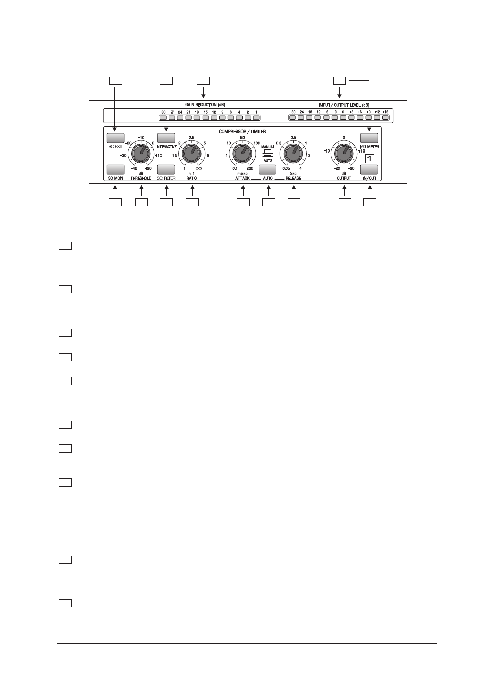
Fig. 2.3: Control elements of the compressor section
5
The THRESHOLD control sets the threshold point for the compressor section. It has a range of -40 to
+20 dB. If the channel is switched to INTERACTIVE mode (Interactive Knee Adaptation), a Soft Knee
characteristic is applied to the signal exceeding the threshold point by a maximum of 10 dB. Above
10 dB, the signal would experience Hard Knee compression.
6
The RATIO control determines the ratio between the input and output level for all signals exceeding the
threshold point. If the INTERACTIVE mode is used, this control determines the ratio between input and
output levels for signals exceeding the threshold point by more than 10 dB. The control range can be
adjusted from 1:1 to oo:1.
7
The ATTACK control determines the rate by which the compressor responds to the signal which
exceeds the threshold. This control can be adjusted from 0.1 to 200 milliseconds.
8
The RELEASE control determines the rate that the compressor returns to unity gain after falling below
the threshold level. This control can be adjusted from 0.05 to 4 seconds.
9
By activating the AUTO switch, the ATTACK and RELEASE controls are disabled and the attack and
release rates are automatically derived from the program material. This function allows for unobtrusive
musical compression of signals or mixes with widely varying dynamics. Only if set to MANUAL the
settings of the attack and release controls will function.
10
The OUTPUT control allows for the increase or decrease of the output signal by a maximum of 20 dB.
Thus, a level loss due to the compression or limiting process can be compensated for.
11
When activated, the SC EXT switch severs the connection between the audio input and the sidechain
path, whilst at the same time allowing an external signal to be sourced at the SC RETURN jack on the
rear panel.
12
Using the SC MON switch will enable you to connect the sidechain control signal to the audio output,
whilst at the same time muting the audio input. This function provides you with the ability to monitor the
sidechain signal that is returned via inserted equalizers or other external processors. The SC MONITOR
function will assist you with tuning equalizer parameters for example.
+
Please note when the SC MON switch is engaged, the audio processing facility of the respec-
tive channel is disabled. When this function is active, a visual indication will be provided by
the switches LED, which will blink.
13
The IN/OUT switch activates the corresponding channel. This switch acts as a so-called hard-bypass,
which means that when the switch is OUT, the input jack is directly linked to the output jack. Normally,
this switch is used to perform a direct A/B comparison between the unprocessed and the compressed
or limited signals.
14
Press the INTERACTIVE switch to change from hard knee to IKA characteristics. IKA provides a very
subtle and musical compression of the program material and should therefore be used whenever
compression is expected to be more or less inaudible.
2. CONTROLS