3 x-over panel, X-over panel – dB TECHNOLOGIES DVA NETWORK 1.2 Device Plugins Manual User Manual
Page 13
12/17
Rev 1.0
Digital Out Source
This option allows to select the audio source that will be forwarded to the connector AES/EBU OUT (digital
output)
Analog In: Audio signals sourced from analog inputs
Digital In: Audio signals sourced from digital inputs
Output 1-2: Audio signals sourced from outputs 1 and 2
Output 3-4: Audio signals sourced from outputs 3 and 4
Output 5-6: Audio signals sourced from outputs 5 and 6
Input A-B link
It allows to configure the inputs in stereo and joined modes, so that all the filters, compressors, delays,
volumes, ... of the two inputs will have the same values.
If active,
“LINKED” button will light up red.
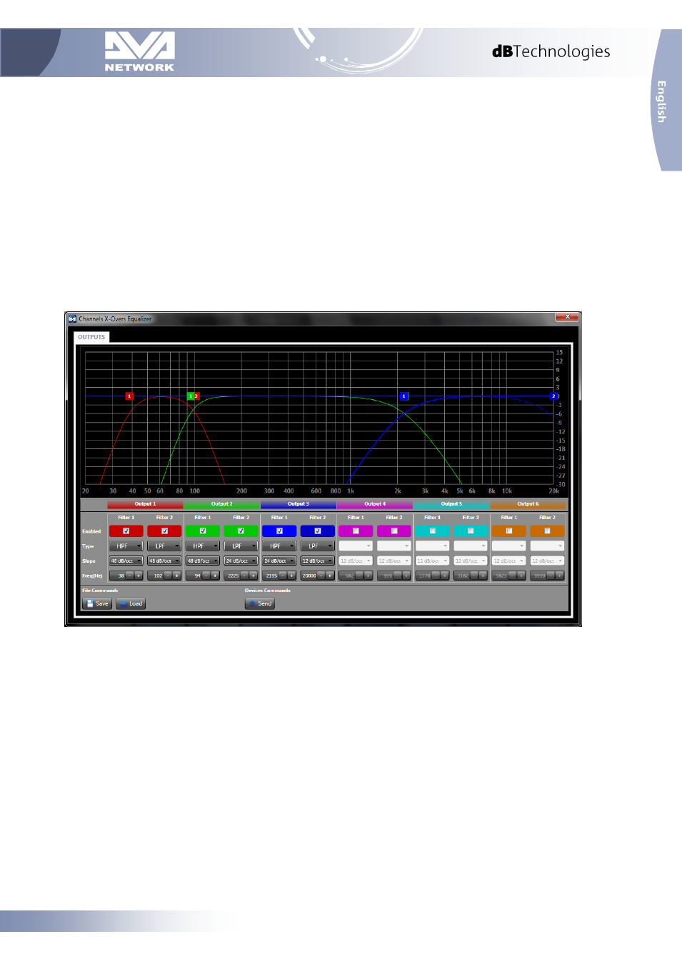
5.3 X-Over Panel
This window allows to select for each output a low pass filter and an high pass filter for each output, or to
create a band-pass filter via the combination of both.
Graphic filters of the individual outputs are identified using the colors shown in the configuration menu. The
configuration can be performed directly on the graph, by moving the relevant square colored cursor with the
mouse, or analytically by inserting the data in the option boxes.
Option boxes are composed by the following fields:
Enabled: Activate the filter.
Type:
HPF: High-pass filter. Set to allow only the part of audio signal above the cut-off frequency
LPF: Low-pass filter. Set to allow only the part of audio signal below the cut-off frequency
Slope: To select the attenuation slope of the audio signal on the basis of the desired attenuation.
The higher the signal slope, at the same cut-off frequency, the greater the signal selection.
Freq (Hz): To set the passing frequency for the lower frequencies only (low-pass filter) or the higher
frequencies only (high-pass filter).