Active line array module – dB TECHNOLOGIES DVA Series User Manual
Page 5
DVA T12
Active Line Array Module
8
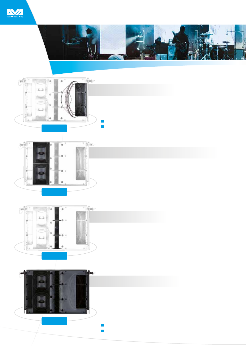
Extended low-end performance
A 12“ neodymium woofer in a band-pass housing covers the low frequency range.
Remarkably powerful, it packs an assertive punch that reaches down to 60 Hz to
enable fullrange applications. The 12“ woofer is slanted inside the housing, giving
the cabinet a lean, unobtrusive look.
12“ neodymium woofer
Fullrange capability from 60Hz up
Accurate and awesomely efficient midrange response
The DVA T12‘s two 6.5“ neodymium midrange are placed close together to maximize
coherent coupling and response for those critical midrange frequencies. The
speaker resides in a sealed basket to optimize the displacement volume. This makes
the midrange even more responsive.
With a high BL factor, it reacts far faster to transients and renders each attack with
awesome accuracy. Both 6.5“ midrange are equipped with an optimized phase plug
and feed into a frontloaded horn to achieve a uniform coverage pattern.
High-definition top end
The 1“ neodymium HF drivers feature 1.4“ Mylar diaphragms. Exceptionally light
and responsive, they deliver richly detailed signals with remarkably linear frequency
response. Specially developed for use in line arrays, these ultra compact drivers may
be deployed in very close proximity to one another. This is essential to minimize
interference in such arrays.
The DVA T12 is loaded with three HF drivers tuned specifically for the
custom designed array horn. This combination maximizes the coupling of
the drivers‘ outputs and extends the range of the HF signal.
Consistent coverage pattern
The DVA T12 features constant directivity horns, HF drivers, and midrange speakers
optimized to deliver a uniform 100°-by-10° coverage pattern.
The DVA makes the most of two acoustical effects to help distribute SPL evenly.
One is the vector addition of individual horns‘ output, with the other being cy-
lindrical wave formation. The coverage pattern may be adapted to suit the sound
reinforcement application by varying the length of the array and adjusting the splay
between individual components.
Uniform 100°-by-10° coverage pattern
Evenly distributed SPL
T12
LF
T12
MF
T12
HF
T12