Dascom 7010 Cutter Installation Guide User Manual
Page 6
– 6 –
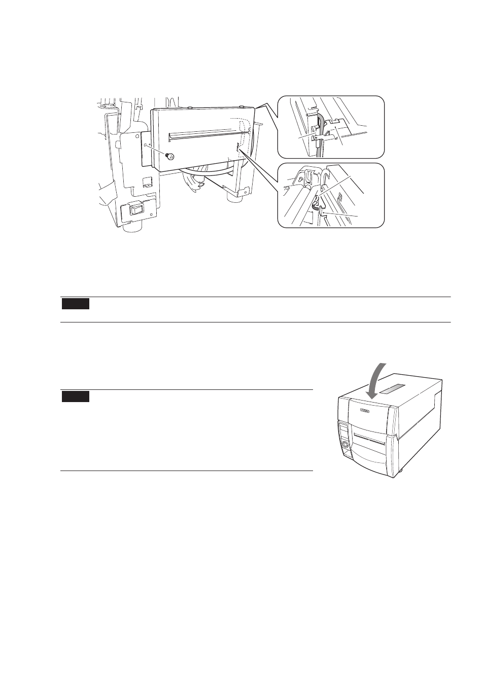
(12) Insert the claw on the right side of the auto-cutter unit into the notch on the printer,
then fix it in place with the attached screw (1).
(13) Attach the front center cover from step 9 in its original position. (2 screws)
(14) Attach the front right cover removed at step 6 in its original position. (2 screws)
(15) Attach the operation panel removed at step 5 in its original position. (3 screws)
Note
Be sure to connect the flexible cable that you disconnected as it was formerly
connected. The blue side
.
s
d
r
a
w
p
u
s
i
p
i
t
e
h
t
f
o
(16) Attach the front top cover from step 4 in its original position. (2 screws)
(17) Close the top cover.
(18) Connect the power cord and turn on the power switch
on the printer.
Note
Removing the auto-cutter unit
To remove the auto-cutter unit from the printer,
follow the installation steps in reverse order. If the
screws that fasten the auto-cutter unit are
removed, the unit may fall from the printer, so
hold the auto-cutter unit with your hand while
loosening the fastening screws.
Be sure to pass the cable
between the metal plate and
the pulley cover.
Metal
plate
Pulley cover
Notch
Claw