Final assembly, Wiring instructions, Double piggyback float switch installations – Clarus Environmental Turbine STEP Systems User Manual
Page 7: Fig. 12
7
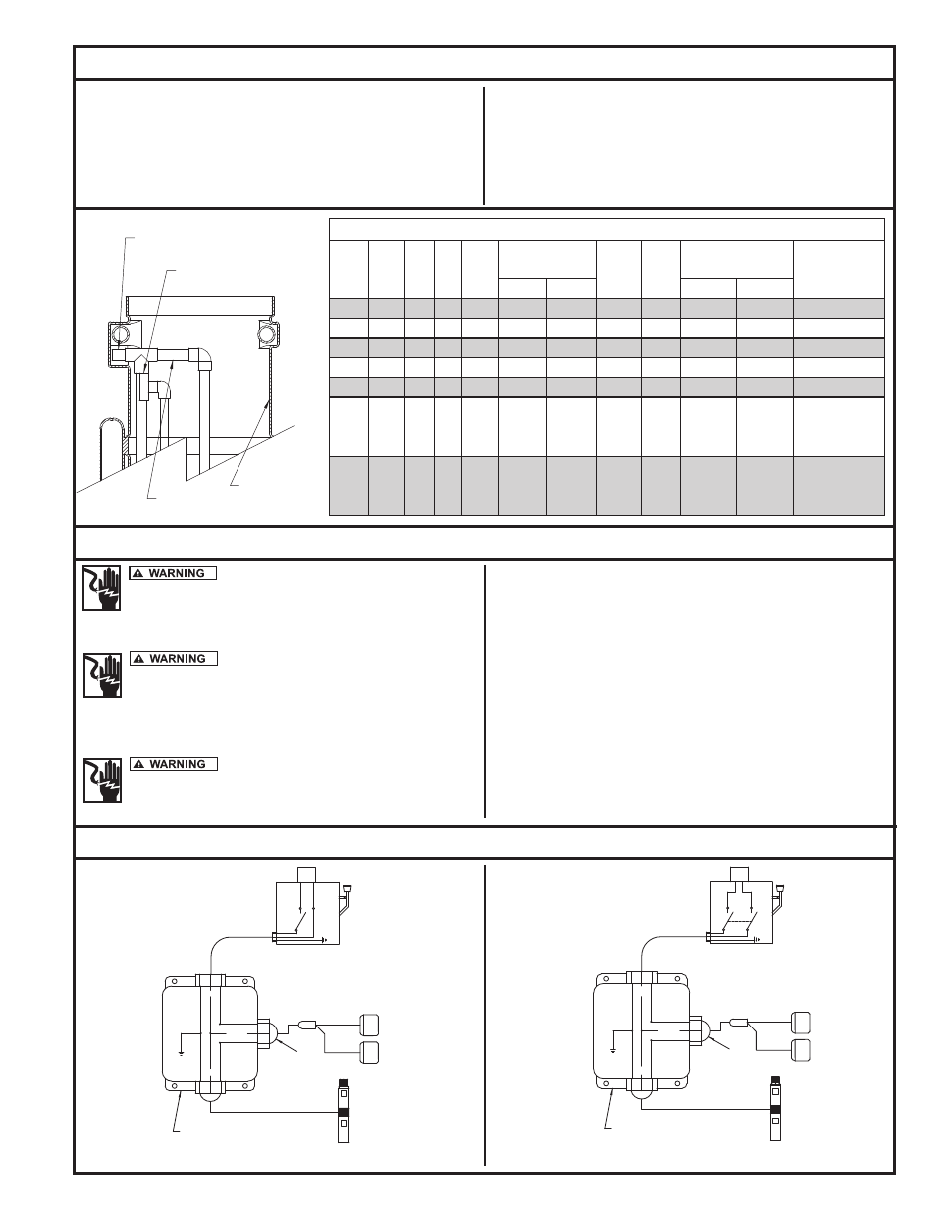
Final Assembly
Electrical Data for Clarus Environmental Turbine Effluent Pumps
HP
Volts
Ph
Hz
S.F.
Maximum
Locked
Rotor
Amps
KVA
Code
Fuse/Circuit
Breaker Amps
Winding
Resistance
Line to Line
Amps
Watts
Std.
Delay
1/2
115
1
60
1.6
12
970
64.4
R
30
15
1.0 - 1.3
1/2
230
1
60
1.6
6
970
32.2
R
15
8
4.2 - 5.2
3/4
230
1
60
1.5
8
1325
40.7
N
20
10
3.0 - 3.6
1
230
1
60
1.4
9.8
1600
48.7
N
25
11
2.2 - 2.7
1 1/2
230
1
60
1.3
13.1
2250
56.8
L
35
15
1.5 - 1.9
2
230
1
60
1.25
Y 13.2
B 11.9
R 2.6
2650
51.0
G
30
15
1.6 - 2.3 M
5.2 - 7.15 S
3
230
1
60
1.15
Y 14.0
B 14.5
R 4.5
3650
82.0
G
45
20
.9 - 1.5 M
3.0 - 4.9 S
FILTER HOLDER
FILTER TANK
ATTACH FLOAT TREE RIGHT BELOW
THE FILTER HOLDER FITTING
TILT FILTER HOLDER TO LOCATE
IN ANTI-FLOTATION POCKET
SK2416
Fig. 12
Wiring Instructions
16. Place the filter holder assembly down in the pump vault, tilting it
toward the pump well side to allow the handle to be placed into the
anti-flotation pocket (see Fig. 1 & 13).
17. Place the float tree assembly down into the pump vault. The bottom
of the float tree must go into the top of the filter holder. Snap the
top of the float tree to the filter holder handle (see Fig. 1 & 12).
18. Connect the pump, floats, alarms and control panels. Follow in-
stallation instructions and wiring diagrams supplied with each.
19. After wiring, fill the septic tank with water. This must be done to
check the pump, float operating levels and the alarm. Be sure the
floats do not hang up during operation! Do not fully empty
the septic tank of water to help prevent float-out.
"Risk of electrical shock" Do not remove
the power supply cord and strain relief or connect conduit di-
rectly to the pump. Installation and checking of electrical cir-
cuits and hardware should be performed by a qualified and licensed
electrician.
For your protection, make certain that the
pump ground wire is properly connected to the ground
wire in the incoming power line. Test for ground at the junc-
tion box using an Underwriters Laboratory listed circuit ana-
lyzer which will indicate if the power, neutral and ground wires are cor-
rectly connected.
In 230 VAC pump installations, one side of
the line going to the pump is always hot. This condition exists
if the switch is on or off. Install a double pole disconnect on all
230 VAC pump circuits.
GENERAL WIRING RECOMMENDATIONS
• Follow the correct wiring diagram for your system.
• Use an auxiliary alarm with the double piggyback float switch op-
tion or any other control method that does not include a high water
alarm. Install the alarm inside the house or in a weather protected
location per installation instructions with the alarm kit. Make sure
the alarm is plugged into a different circuit than the pump circuit.
• If a junction box is being used, follow the installation instructions
and wiring directions with the junction box or follow the directions
below. All wiring, from the power source to the pump, must conform
to the National Electrical Code.
• Be sure to leave a sufficient amount of cord so the filter can be
serviced without disconnecting the cordage from the junction box
(see maintenance section).
LIQUID-TIGHT
CONNECTOR
G
N
L1
115V
PUMP
G
G
L1
G
115V
POWER
SOURCE
BLACK
RED
WHITE
N
115V
SWITCH
L1
N
JUNCTION BOX
RED
LIQUID-TIGHT
CONNECTOR
G
L2
L1
230V
PUMP
230V
POWER
SOURCE
L1
G
G
BLACK
WHITE
L2
L1
230V
SWITCH
G
L2
JUNCTION BOX
120 VAC
230 VAC
Double Piggyback Float Switch Installations
SK1837A
SK1837B
© Copyright 2011. All rights reserved.