Timed dosing applications, Fig. 9 fig. 10, Fig. 11 – Clarus Environmental Turbine STEP Systems User Manual
Page 6: Fig. 8
6
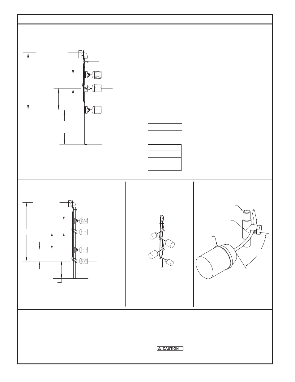
HIGH WATER ALARM
TIMER OVERRIDE
5" MIN.
LOW LEVEL CUTOUT
8" MIN.
REDUNDANT OFF
5" MIN.
30.5" MAX.
TIMED DOSING WITH REDUNDANT OFF
3.5" MIN.
(1" ADDED FOR SAFETY)
SEPTIC TANK MIN. INLET HEIGHT 41"
TOP OF FLOAT TREE
NYLON CABLE TIE
TOP OF FILTER HOLDER
TO THE FLOAT TREE USING TAPE OR
FLOAT CORD HOLDER MUST BE ATTACHED
NOTE: IN ALL CASES. THE LOOSE CORD ABOVE
NYLON WIRE TIES.
NOTE: FLOATS ARE 90° OPPOSED AND
LOCATED OPPOSITE THE INSIDE
WALL OF THE PUMP VAULT.
3 1/2" TETHER
FLOAT
CORD HOLDER
FLOAT TREE
Fig. 9
Fig. 10
SK2434F
SK2504
SK2415
Fig. 11
Timed Dosing Applications
Fig. 8
5" MIN.
8" MIN.
LOW LEVEL CUTOUT
HIGH WATER ALARM
TIMER OVERRIDE
26.5" MAX.
TIMED DOSING
7.5" MIN.
(1" ADDED FOR SAFETY)
SEPTIC TANK MIN. INLET HEIGHT 40"
TOP OF FLOAT TREE
NYLON CABLE TIE
TOP OF FILTER HOLDER
SK2434E
If using a timed dosing panel, the floats should be set as follows:
Timed dosing without redundant off (see Fig. 8). Timed dosing with
redundant off (see Fig. 9).
If the system is dosing a collection system drain field, media filter,
wetland or some other secondary wastewater treatment system, the
ideal dosing pattern should be known and applied.
The alarm must be activated at or before the point when the effluent
level reaches the bottom of the inlet pipe.
Record the actual settings measured from the top of the float tree in
the table provided for future reference.
Float switch distance from top of the float tree w/o redundant off.
Alarm - Black (below or even w/ bottom of inlet)
Timer override - Gray (varies)
Low level cutout - Gray (maximum 26½")
Float switch distance from top of the float tree with redundant off.
Alarm - Black (below or even w/ bottom of inlet)
Timer override - Gray (varies)
Low level cutout - Gray (varies - maximum 25½")
Redundant off - Black (maximum 30½")
Small dimension float switches are recommended
in all applications to prevent hang-ups.
13. Measure and mark all float locations on the float tree. Install the
cord holders on the float tree. Place one at each marked location
rotating them approximately 90° apart in two quadrants (see Fig.
10).
14. Unpack variable level float switches from system. Remove and
discard any float holders/clamps attached to float switch cords. Cut
any piggyback plugs from any float switches. Measure 3½” from the
float switch on the cord and mark this spot. Using the appropriate
float diagram section (see Figs. 6, 7, 8 & 9), assemble each float
cord through the float holder and hand tighten (see Fig. 11).
15. Secure float cords to top of the float tree to prevent hang-ups (see
Fig. 10).
© Copyright 2011. All rights reserved.