Fig. 2 fig. 3, Fig. 4 fig. 5 – Clarus Environmental Turbine STEP Systems User Manual
Page 4
4
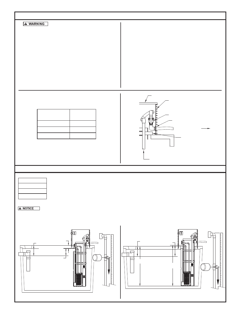
SINGLE UNION BALL VALVE
FILTERED EFFLUENT
PIPE SEAL
CLARUS ACCESS RISER (24" SHOWN)
LID
FROM PUMP
HANGER PIPE
DISCHARGE
Do not lower the pump by the power cord.
10. If supplied or required, attach the check valve to the pump outlet.
Disconnect the Clarus Environmental flexible pipe discharge as-
sembly at the union on the ball valve. Connect the long part of the
discharge assembly to the pump outlet or check valve with the pump
set up outside the pump vault. If check valve is used, weephole
should be below check valve.
11. Tie off the power cord by strapping it to the upper end of the discharge
pipe. Make certain the cord cannot become entangled or obstruct
the movement of the floats. Lower the pump by the discharge pipe
into the right or left pump well of the pump vault (see Fig. 1).
SK1833
Fig. 2
Fig. 3
DISCHARGE PIPE
ASSEMBLY
HOLE SAW
REQUIRED
1"
1¾"
1¼"
2"
2"
3"
Top of septic tank to liquid level (bottom of outlet).
Top of septic tank to bottom of inlet.
Top of septic tank to inside floor
STEP system pump vault inlet height (to the center of the inlet).
13"
52 1/2"
51"
EXAMPLE:
51 - 13 = 38
52 1/2 - 38 = 14 1/2
(SO THE ALARM FLOAT SHOULD
BE SET LOWER THAN 14 1/2"
FROM THE TOP OF THE FLOAT
ROD)
11
10
9
8
7
5
4
3
2
6
18
17
19
13
14
15
16
1
1
12
21
20
22
14 1/2
TOP OF THE FLOAT TREE
14"
3 1/2"
EXAMPLE:
14 - 3 1/2 = 10 1/2
(SO THE ALARM FLOAT SHOULD
BE SET LOWER THAN 10 1/2"
FROM THE TOP OF THE FLOAT
ROD)
10 1/2"
22
21
20
19
18
17
6
11
16
15
14
13
12 1
7
8
9
10
1
2
3
4
5
TOP OF THE FLOAT TREE
Fig. 4
Fig. 5
SK2435A
SK2435B
Discharge Pipe and Pump Installation
Float Tree Assembly
The alarm must be activated at or before the point when the effluent level reaches the bottom of the inlet pipe. If the STEP
system is being installed in an existing septic tank, the outlet pipe must be plugged.
12. Reconnect the union loosely to see approximately where to install the
pipe seal through the riser wall. Remove the pump by the discharge
assembly. Drill the appropriate hole through the riser wall (see Fig.
2). Install the pipe seal through the riser wall to prevent ground
water intrusion. Disconnect the union on the discharge assembly
and install the flexible pipe through the pipe seal with the union
ball valve on the inside of the riser (see Fig. 3). Solvent weld the
flexible pipe to the lateral field piping using PVC pipe cement.
13. Lower the pump by the discharge assembly back into the appropriate
pump well in the pump vault. Adjust the piping using the threaded
elbows and flexible piping of the discharge assembly to achieve
proper fit. Securely connect the union on the ball valve. Repeat
steps 9-12 for a second pump in a dual pump system.
© Copyright 2011. All rights reserved.