3 sensor installation, 1 sensor insulator installation, 2 sensor alignment sheet installation – CiDRA Elevated Temperature Sensor Head User Manual
Page 7: Sensor installation -3, Sensor insulator installation -3, Sensor alignment sheet installation -3, Figure 1, Sensor polyimide sheet installation -3, Warning, Caution
2.3 Sensor
Installation
2.3.1
Sensor Insulator Installation
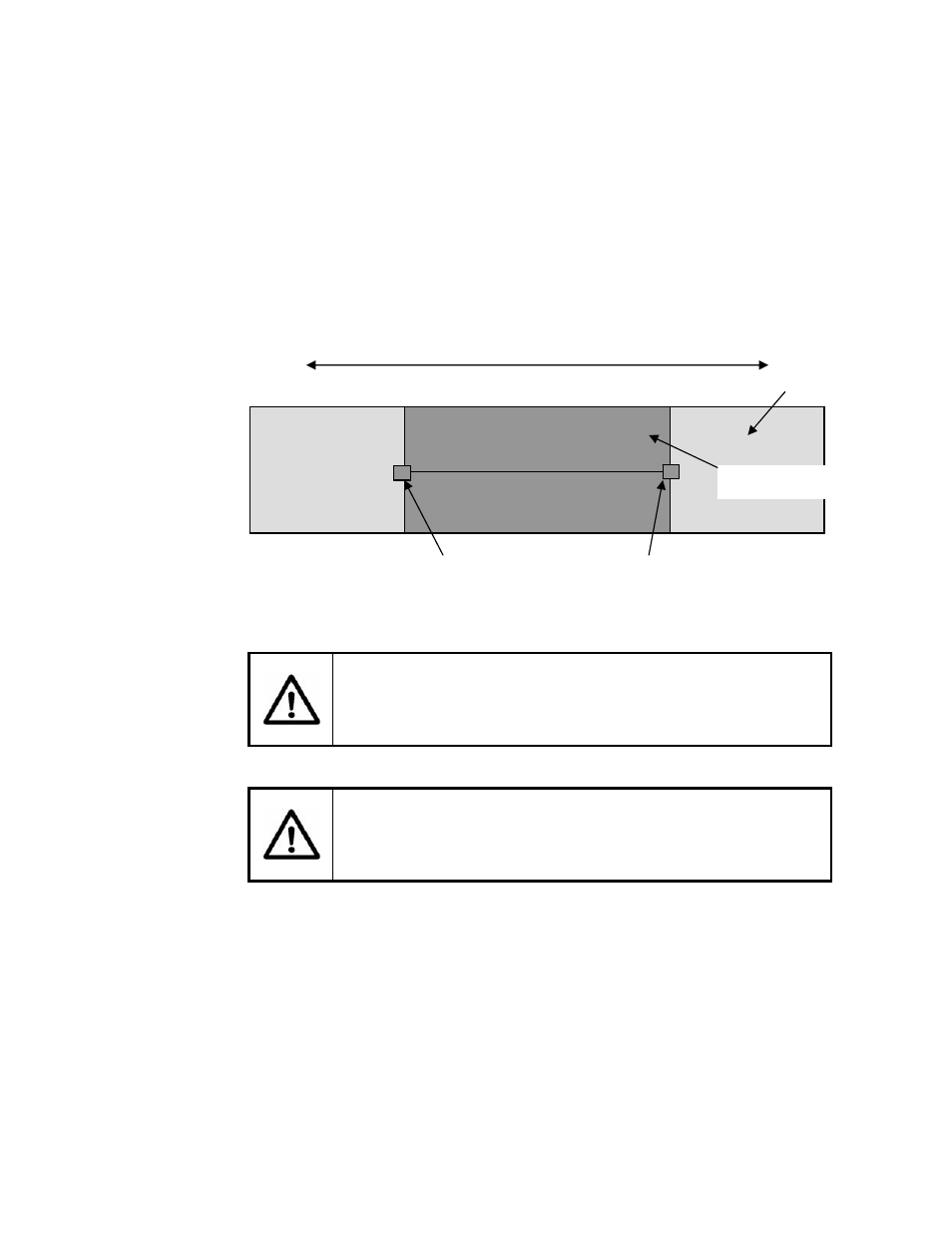
Properly clean the process pipe as described in the VF-100 or GVF-
100 Manual along a 36 inch length of process pipe.
Wrap the polyimide (Kapton) sheet around the pipe such that it is in
the middle of the cleaned section. (The goal is to electrically insulate
the alignment sheet from the pipe.) Temporarily secure the sheet with
tape (if needed) outboard of where the sensors will be located.
Figure 1
Sensor Polyimide Sheet Installation
2.3.2
Sensor Alignment Sheet Installation
WARNING
Use care when handling alignment sheet, sharp edges may
cause cuts.
CAUTION
Use care when handling alignment sheet, do not damage wires
attached to alignment sheet.
Attach alignment sheet to pipe using 4 springs. The seam of
alignment sheet should be aligned such that it will be as close as
possible to the preamplifier housing on the cover when the cover is
installed. It is preferred that the preamplifier housing is oriented “up”
(12 o’clock position) for horizontal pipe installations.
Remove the tape (if used) from the Kapton sheet.
Note: For vertical installations install the cover inner support ring ½-
inch from the upper edge of the Kapton sheet.
36 inches cleaned
Process pipe
Polyamide sheet
Tape outboard of sensor location
21020-01 Rev 01
Page 2-3