5 sensor pre-amplifier connections, 1 sensor band to pre-amplifier connection, Sensor pre-amplifier connections -14 – CiDRA Elevated Temperature Sensor Head User Manual
Page 18: Sensor band to pre-amplifier connection -14, Figure 15, Pre-amplifier housing feed-through -14, Figure 16, Pre-amplifier top and bottom view -14
2.5
Sensor Pre-Amplifier Connections
2.5.1
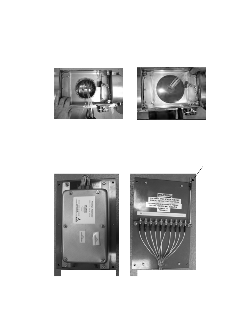
Sensor Band to Pre-Amplifier Connection
Carefully feed the eight sensor wires and wires #9 and #10 from the
sensor band through the slot in the sensor band feed through.
Reinstall the feed-through in the pre-amplifier housing.
Figure 15
Figure 16
Pre-amplifier Housing Feed-through
Reinstall the fiberglass insulation in the pre-amplifier housing and
route the sensor band wires on top of the insulation.
Lay the pre-amplifier in the pre-amplifier housing with the bottom side
facing up.
Sensor shorting plug (may be
mounted in alternate position)
Pre-amplifier top side
Pre-amplifier bottom side
Pre-amplifier Top and Bottom View
21020-01 Rev 01
Page 2-14