chiliGREEN K8VHA Pro User Manual
Page 16
12
12
12
12
12
English
English
English
English
English
BIOSTAR Motherboard
(10) Power Source Selection for USB: JUSBV1/ JUSBV2/ JUSBV3/ JUSBV4
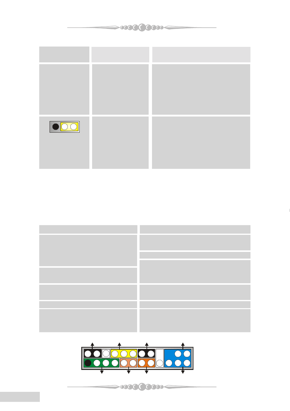
(11) Front Panel Connector: JPANEL1
The connector is for electrical connection to the front panel switches and LEDs.
JUSBV1/ JUSBV2/
Assignment
Description
JUSBV3/ JUSBV4
JUSBV1: 5V for USB port located at
the JUSBLAN1 connector port.
JUSBV2: 5V for USB port located at
the J1394_USB1 connector port.
JUSBV3: 5V for USB port located at
the JUSB3 connector port.
JUSBV4: 5V for USB port located at
the JUSB4 connector port.
Pin 1-2 close
+5V
JUSBV1: JUSBLAN1 port powered
with standby voltage of 5V.
JUSBV2: J1394_USB1 port powered
with standby voltage of 5V.
JUSBV3: JUSB3 port powered with
standby voltage of 5V.
JUSBV4: JUB4 port powerered with
standby voltage of 5V.
1
3
Pin 2-3 close
+5V Standby
Voltage
Note: 1. In order to support this function “Power-on the sytem via USB
devices”, "JUSBV1/JUSBV2/ JUSBV3/ JUSBV4" jumper cap should
be placed on pin 2-3 respectively.
2. Use +5V Standby Voltage for S3 mode.
Pin Assignment Function Pin Assignment Function
1 +5V 2 Sleep Control Sleep Button
3 NA Speaker 4 Ground
5 NA Connector 6 NA NA
7 Speaker 8 Power LED (+) Power LED
9 HDD LED (+) Hard Drive 10 Power LED (+)
11 HDD LED (+) LED 12 Power LED (-)
13 Ground Reset 14 Power Button Power-on Button
15 Reset Control Button 16 Ground
17 NA 18 KEY
19 NA IrDA 20 KEY IrDA Connector
21 +5V Connector 22 Ground
23 IRTX 24 IRRX
SPK
PWR_LED
HLED
SLP
RST
2
24
IR
1
23
IR
ON/OFF
(+) (-)
(+)
(-)
(+)