Blue Sea Systems 8410 AC Digital Meter Panel - 240V AC User Manual
Page 3
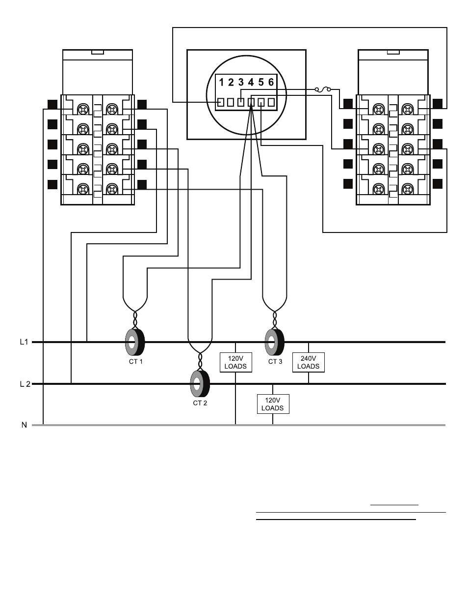
Caution
The wiring complexity is naturally increased by the addition of two more
CT’s and sensing two additional voltages. Be careful not to
accidentally switch the system voltage on to terminal 4 and 5, the
current sensing inputs, as it will suffer serious damage. If during
startup and testing there is a question about the values being displayed
bypass the switch and feed the input directly to the appropriate terminals
on the meter. This way, correct operation of the meter can be verifi ed as
a separate issue from the correct wiring of the switched inputs.
Additional information is also available at www.bluesea.com under the
technical
tab.
Notes
1. See installation manual for PN 8247 AC Digital Multimeter.
2. See Warnings! Disconnect all AC power originating on or off the
vessel. This includes inverters, generators, shore power attachments
and any other device capable of supplying AC power to the ship’s
circuits.
3. Select a mounting location which is protected from water on the panel
front and back and is not in an area where fl ammable vapors from
propane, gasoline or lead acid batteries accumulate. The circuit
breakers used in marine electrical panels are not ignition protected
and may ignite such vapors.
Wiring Diagram
8247 Digital Meter Wiring
For 120/240 Volt AC
2
4
8
6
12
10
16
14
20
18
3
1
5
7
9
11
13
15
17
19
14
20
18
2
6
10
16
4
8
12
13
15
17
19
1
3
5
7
9
11
Back of Meter
Top View
Bottom View
Pre-wired
AC Rotary Switch
AC Rotary Switch
Document 6961 Rev.E
Page 3 of 3