Installation, Continued) – Blue Sea Systems 8132 AC Toggle Source Selector [European] User Manual
Page 2
Installation
(continued)
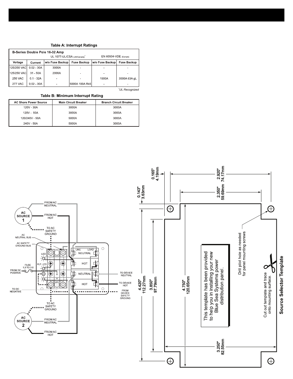
4. Interrupt
Ratings
If complete ABYC compliance is desired, verify that the circuit breaker
supplied in this panel as shown in Table A meets the interrupt rating
requirements of Table B.
7. Testing
@
Connect the vessel’s shore power and verify the Reverse Polarity
light is not illuminated. If the red Reverse Polarity light is on then
either the hot and ground or the hot and neutral wires have been
crossed. Starting at the panel, trace the connections back as far
as necessary to locate the error.
@
Using a multimeter where the power source is connected to the
panel verify:
a.
230 volts between hot and neutral
(nominal, this may vary depending on source voltage)
b.
230 volts between hot and ground.
c.
0 volts between neutral and ground.
Related Products from Blue Sea Systems
• PanelBack Insulating Covers
• High Amperage Fuses and Circuit Breakers for positive feed wires
• High Amperage Battery Switches
• Terminal Blocks and Common Bus Connectors
• AC Distribution Panels
• DC Distribution Panels
• AC and DC Digital and Analog Voltmeters and Ammeters
Useful Reference Books
Calder, Nigel, 1996:
Boatowner’s Mechanical and Electrical Manual,
2nd edition, Blue Ridge Summit, PA: TAB Books, Inc.
Wing, Charlie, 1993:
Boatowner’s Illustrated Handbook of Wiring,
Blue Ridge Summit, PA: TAB Books, Inc.
5. Installation of Backlight System
The backlight board is a DC device. When installing it in an AC panel
both wire leads must be connected to an appropriate DC source and
ground.
Connect the yellow negative wire to a DC ground. Connect the red
positive wire to any DC positive supply, usually a switch that controls
the vessel’s other nighttime illumination.
6. Apply circuit labels and mount panel
Apply a label for each circuit form the 10 basic labels provided. Fasten
the panel to the mounting surface.
Wiring Diagram
AC Source Selector Panel
PN 8132 / PN 3132 / PN 8161 / PN 3161