Installation, Continued) – Blue Sea Systems DC Power Distribution Panel 5,10,13 Position User Manual
Page 2
Installation
(continued)
7. Install branch circuit wires
Determine the proper wire size for each branch circuit using the
guidelines in step 4. Verify that the standard 15 amp circuit breakers
installed in the panel are large enough for each branch circuit. Remove
and replace with a higher amperage any that are undersized. Connect
the positive (red) branch circuit wires to the load terminals of each
circuit breaker. Connect each negative (black) branch circuit wire to the
DC Negative Bus. DO NOT CONFUSE THE DC NEGATIVE BUS
WITH THE DC GROUNDING BUS.
8. Optional - install grounding system wire
The grounding wire (bare, green or green with yellow stripe and
normally non-current carrying) should not be confused with the
negative ground wire (black or yellow and normally current carrying).
In
Boatowner’s Illustrated Handbook of Wiring, Charlie Wing identifi es
three purposes of DC Grounding:
1.
Holding conductive housings of low voltage (under 50 volts) DC
devices at ground potential by providing a low resistance return
path for currents accidentally contacting the device cases.
2.
Providing a low resistance return path for electrical current,
preventing stray currents that may cause corrosion.
3.
Grounding metal electrical cases to prevent emission from inside
or absorption from outside of radio frequency noise (RFI).
ABYC requires that grounding wires be sized no smaller than one wire
size under that required for current carrying conductors supplying the
device to which the grounding wire is connected.
A full treatment of this subject is not possible within the scope of these
instructions and there is controversy surrounding the general subject of
DC bonding, of which DC grounding is a component. It is suggested
that installers not familiar with this subject consult one of the reference
books listed elsewhere in these instructions.
8. Installation of Backlight System
Connect the yellow negative wire to the panel negative bus.
To activate the label lights by the boat’s battery switch, connect the red
positive wire to the DC panel positive bus.
To activate the label lights by an independent switch or breaker, connect
the red positive wire to the load side of the switch or breaker.
9. Apply branch circuit labels and mount panel
Apply a label for each of the branch circuits from the 30 basic labels
provided. If the appropriate label is not included, the Extended Label
Set of 120 labels may be ordered from your marine supplier (PN 8039).
Individual labels are also available from Blue Sea Systems for specifi c
applications. Refer to the label order form for a complete listing of
individual labels. Fasten the panel to the mounting surface using the
panel mounting screws supplied with the panel.
10. Testing
Reconnect the main positive cable to the battery terminals and turn the
main switch on to supply power to the panel. Turn on all branch circuits
and test the voltage at the panel. Compare this voltage to the battery
terminal voltage to determine that the voltage drop is within 3%. With
all branch circuits still on, test the voltage at one device on each circuit
to determine that there is a 3% or 10% drop as is appropriate.
Note
This Blue Sea Systems electrical distribution panel is furnished with 15
amp AC/DC circuit breakers. This rating was selected to minimize the
need for removing the panel’s circuit breakers and reinstalling different
size circuit breakers. As shown in the Wire Sizing Chart included with
these instructions, even 16 AWG wire, which is the minimum wire size
recommended by ABYC, has an allowable amperage greater than 20
amps. Additionally, it would be rare to have more than 15 amps of current
fl owing in any one circuit. Therefore, 15 amp circuit breakers will satisfy
the vast majority of marine circuit protection situations.
Optional Branch LED’s
This panel is supplied with LED’s pre-installed in all optional branch
positions. For future expansion of the panel remove the positive leg of
the LED from the negative bus and connect it to the load side of the
corresponding branch circuit breaker.
The Purpose of a Panel
There are fi ve purposes of a marine electrical panel:
• Power distribution
• Circuit (wire) protection
• Circuit ON/OFF switching
• Metering of voltage and amperage (In panels with meters)
• Condition Indication (circuit energized)
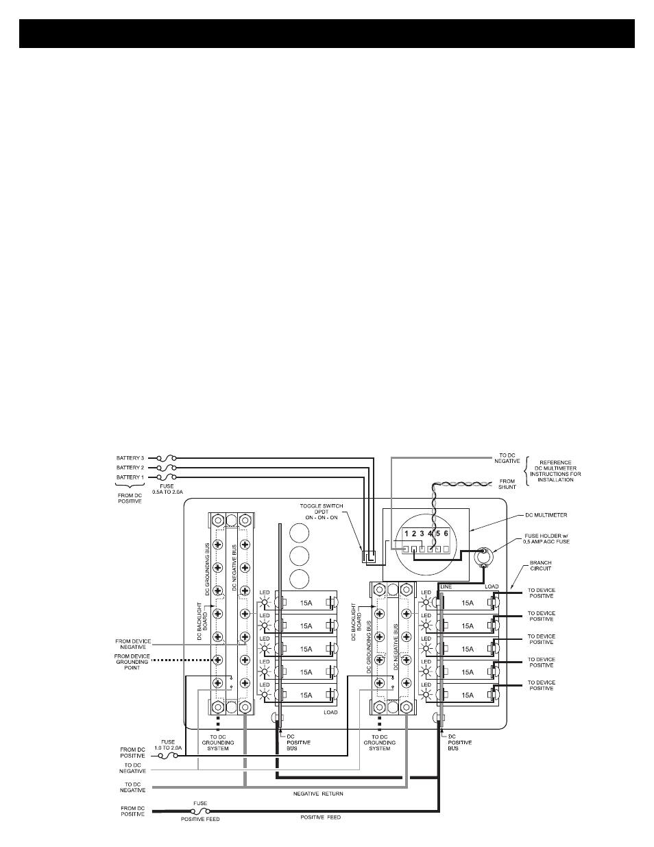
Wiring Diagram
DC Power Distribution Panel
with DC Multimeter
(PN 8403 / PN 3403 shown for reference)