Blue Sea Systems 8407 AC Main + 11 Positions User Manual
Page 2
8731 Rev.13
Blue Sea Systems Inc.
425 Sequoia Drive Bellingham, WA 98226 USA
p (360)738-8230 f (360)734-4195
www.bluesea.com
NOTE:
Use 16 AWG for all meter wiring.
All models require connections to terminals #1 and #3
Terminals
#4 and #5 are used for PN 8238 and PN 8247 only
Wire to terminal #1 (Neutral or L1 for 240V)
---Connects terminal #1 of the meter to the AC Neutral for 120
Volt AC systems. For 240 Volt AC systems this wire is connected to L1, supplying one leg of the 240V AC. When
used in a 240 Volt AC system this wire must be fused with a 0.5A fuse in a holder with appropriate rating.
Terminal #2 is not used.
Wire to terminal #3 (L1 or L2 for 240V)
---This wire and wire to terminal #1 supply power to the meter.
Voltage is measured off these wires as well. This wire must be protected by a fast acting fuse rated at 0.5A. Both
the fuse and fuse holder must carry the appropriate voltage rating.
The wires to terminals #4 and #5 must be a twisted pair to avoid electrical system noise that will affect the
accuracy of current measurement. These may be twisted by hand or by using an electric drill motor, or
twisted pair wire may be purchased from most electrical supply companies. Wires to terminals #4 and #5
provide the mA signal (generated by current flow in the primary wire passing through the CT) to the meter
for current measurement.
NOTE:
The two wires from the CT do not have polarity indicated. The polarity does not make a difference for current
measurement but for Power measurement it does. IF THE POWER NUMBER IS ZERO WHILE THE AMPERAGE
NUMBER DOES NOT EQUAL ZERO REVERSE THE CT SENSE LEADS.
Wire to terminal #4 (Current Transformer Sense)
---This is one of the sense leads from the CT. It must be
a twisted pair with the wire to terminal #5. This wire carries a continuous 50mA under full load and may have
intermittent currents two or three times higher. It must be securely connected under terminal #4 on the back of the
meter. The CT sense leads may be extended up to 25 feet but the connections must be well made as high
resistance connections can affect the accuracy of the current measurement.
Wire to terminal #5 (Current Transformer Sense)
---This is the other sense lead from the CT. It must be a
twisted pair with the wire to terminal #4, and it must be securely connected to terminal #5 on the back of the meter.
Terminal #6 is not used.
Wire by Wire Instructions
Wiring Diagram
Set the meter to display voltage using the
arrow buttons. The function LED will
be on. Hold the button for two seconds to
access the MENU. Use the arrow
buttons to scroll until is in the display.
Press to select the High Voltage Alarm.
V
V
Use the arrow buttons to select
or
(Default OFF). Press the button to save the
selection to memory and continue.
SET
MENU
V
V
Flashing
SET
MENU
High Voltage Alarm -
Press the button when the desired set point
is displayed and the new value will be saved
to memory. Two short beeps will let you know
you have successfully set the new value and
the meter will revert to normal operation.
The present setting will appear in the display
(Default 130.0). If the set point is acceptable,
press the button or wait for 15 seconds and
the meter will revert to normal operation.
Otherwise use the arrow buttons to
select the desired value. For example, press
and hold the right button to scroll up to 250
Volts.
V
V
Flashing
V
V
Flashing
V
V
Flashing
The alarm system is capable of recognizing
more than one alarm condition at a time. If
more than one alarm is set, the meter will
continuously check for each alarm condition.
If an alarm condition occurs while in scan
mode, or while displaying a different
parameter, the display will shift to the alarm
value.
If an alarm occurs, the audible alarm will
sound and the display will alternate between
the type of alarm and the measured value.
Silence by pressing
button. Display will
alternate between the alarm condition and the
value. Every 5 minutes the alarm will give
four beeps and display the alarmed
parameter. This will continue until the alarm
condition is cleared, or the alarm function is
turned off, or the set point changed.
If in Sleep Mode an alarm will “wake up” the
meter and it will function as above. After 10
minutes of no acknowledgment it will re-enter
the Sleep mode. Every 5 minutes it will give
four audible beeps and display the alarmed
condition and measured value for 30 seconds
before returning to sleep mode.
If a second alarm condition occurs while the
first alarm condition is still active, it will also
have to be acknowledged to stop the alarm
sound. The meter will continue to display the
most recent alarm condition. If that alarm
condition is cleared by values returning to
normal, the meter will not indicate the status
of prior acknowledged alarms. Once you have
acknowledged alarms, check all parameters
periodically or reset scan mode to be sure you
are aware of all conditions.
the
Display Alternates
SET
MENU
A
A
W
W
SET
MENU
A
A
Acknowledging an Alarm
Displaying the Code Revision
For customer service convenience, all models
are able to display the revision of software
installed in the meter. To see the software
revision for meters with a single button, press
and hold the center ( ) button. To see the
revision on meters with three buttons, press
and hold the two
buttons. In either
case, the power-up test will be performed and
the software revision will be displayed.
arrow
Mounting Methods
2.270"
57.66mm
0.226"
1.260"
5.74mm
32.00mm
2.625"
66.68mm
2.431”
0.810”
61.75mm
20.57mm
2.896”
73.56mm
0.125"
#4
SCREW
3.18mm
3.375”
85.73mm
PANEL
PLUG
(IF REQUIRED)
INSTALL
FROM
BEHIND
PANEL
STEP 2
STEP 1
PANEL MOUNT
2
REMOVE DRESS BEZEL
BEFORE INSTALATION
1
THROUGH HOLE MOUNT
0.650”
16.51mm
B
U
L
K
H
E
A
D
2.750”
69.85mm
MOUNTS IN 2.00”
50.8mm DIA. HOLE
LOCKING
RING MUST
GO ON
BEFORE
MOUNTING
NUT
NUT
FINGER
TIGHTEN
ONLY!
1.50” MAX
38.1mm
GASKET
SEAL
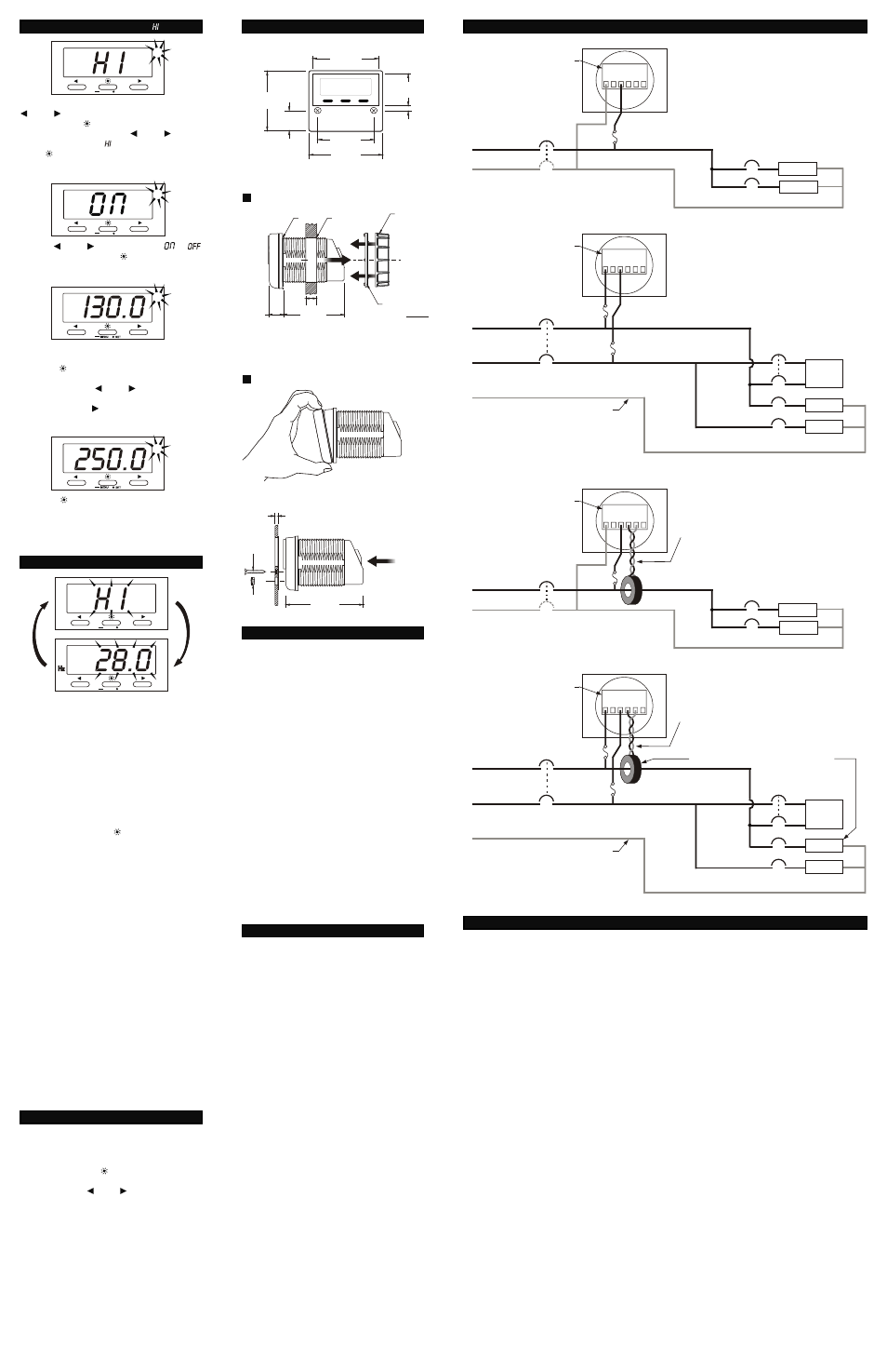
PN 8237/PN 8239
120 Volt System
LINE
NEUTRAL
Main Breaker
1 2 3 4 5 6
LOADS
LOADS
Branch Breakers
Optional 2 pole
Circuit Breaker
(for marine
applications)
Fast Fuse*
0.5-1.0A
BACK OF THE METER
PN 8237/PN 8239
120/240 Volt System
AC L1
AC L2
DO NOT PLACE CT AROUND NEUTRAL
1 2 3 4 5 6
120V LOAD
240V LOAD
LARGER
120V LOAD
SMALLER
NEUTRAL IF PRESENT
Fast Fuse*
0.5-1.0A
Branch
Breakers
Main Breaker
2 pole (typical)
1 pole
1 pole
Fast Fuse*
0.5-1.0A
BACK OF THE METER
Terminal Block
Terminal Block
Warranty
ALL BLUE SEA SYSTEMS DIGITAL METERS
ARE WARRANTED TO BE FREE FROM
DEFECTS IN MATERIALS OR WORKMANSHIP
FOR THREE YEARS FROM THE DATE OF FIRST
PURCHASE.
“DATE OF FIRST PURCHASE” MEANS:
(i) the date on which the product was purchased by
the first retail customer.
(ii) the date on which the first retail customer
purchases a vessel on which the product was
installed.
BLUE SEA SYSTEMS WILL (AT ITS SOLE
DISCRETION) REPAIR OR REPLACE ANY
PRODUCT WHICH IS:
(i) proven to be defective in materials or
workmanship.
(ii) returned to Blue Sea Systems (or its agent)
during the warranty period in accordance with this
warranty.
Replacement products may be new or refurbished
in as-new condition. Such repair or replacement will
be the sole remedy by Blue Sea Systems under this
warranty. Any repaired or replacement product will
be warranted in accordance with this warranty, for
the unexpired balance of the warranty period on the
original product.
PN 8238/PN 8247
120 Volt System
LINE
NEUTRAL
Main Breaker
1 2 3 4 5 6
LOADS
LOADS
Branch Breakers
TWIST WIRES TOGETHER
TO REDUCE NOISE
Optional 2 pole
Circuit Breaker
(for marine
applications)
Fast Fuse*
0.5-1.0A
Current Transformer 150A-50mA
(models PN 8238 and PN 8247 only)
BACK OF THE METER
PN 8238/PN 8247
120/240 Volt System
AC L1
AC L2
DO NOT PLACE CT AROUND NEUTRAL
1 2 3 4 5 6
120V LOAD
240V LOAD
LARGER
120V LOAD
SMALLER
NEUTRAL IF PRESENT
Fast Fuse*
0.5-1.0A
Branch
Breakers
Main Breaker
2 pole (typical)
TWIST WIRES TOGETHER
TO REDUCE NOISE
PLACE CT ON LINE WITH LARGER 120V LOADS
1 pole
1 pole
Fast Fuse*
0.5-1.0A
BACK OF THE METER
Current Transformer 150A-50mA
(models PN 8238 and PN 8247 only)
Terminal Block
Terminal Block
Warranty Registration
Blue Sea Systems is committed to exceptional
customer service. Please allow us to serve you
better by registering your product online at
http://bluesea.com/go/warranty-registration. If you
would prefer to register your product by fax, please
call (360) 738-8230 or Toll Free in the USA and
Canada (800) 222-7617 for a fax-ready Warranty
Registration card.