Wire size – Blue Sea Systems 1408 M-Series Dual Circuit Plus, Main + 3 Position CLB Vertical User Manual
Page 7
Segment 2
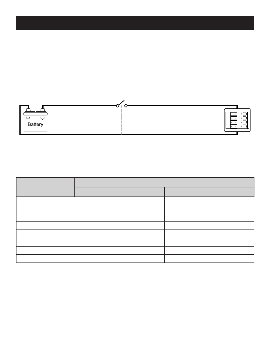
1.5% voltage drop
eg. battery switch to power distribution panel
Segment 1
1.5% voltage drop
eg. battery bank to battery switch
3% voltage drop along entire circuit path
(from power source to load and return)
Segment 1 + Segment 2 = 3% Voltage Drop
WIRE SIZE
DC Circuits:
Use Blue Sea Systems’ DC Circuit Wizard online at
http://dc.circuitwizard.bluesea.com/ to guide you in suitable wire size
selection for each DC Feed, Main, and Branch Circuit.
Voltage drop along a circuit path is cumulative. To achieve suitable voltage
drop along a path consisting of multiple segments, use the DC Circuit Wizard
to assign voltage drop values to each segment that add up to the desired
voltage drop.
Be sure to measure the length of wire from power source to load and return.
Wire Size (AWG)
Allowable Amperage of Conductors
Outside Engine Spaces
Inside Engine Spaces
16
25.0
21.3
14
35.0
29.8
12
45.0
38.3
10
60.0
51.0
8
80.0
68.0
6
120.0
102.0
4
160.0
136.0
2
210.0
178.5
This ABYC table is for wire with 105°C (122°F) insulation rating and no more
than 2 conductors bundled together. It is not suitable for sizing flexible shore
power cords. The values will allow conductors to reach their full 105°C
(122°F) rated temperature.
Many experts in the marine electrical industry recommend using wires that are
one or two sizes larger than shown in the table above to reduce the operating
temperature of the wire.
5
For more information go to www.bluesea.com
ABYC E-11 Table IV 105°C (122°F) Wire
AC Circuits:
For each AC Feed and Branch circuit, the ABYC table below
lists the minimum wire size.