Online manual not for resale purposes – BLITZ R-FIT-Fuel Intensity Tracer User Manual
Page 22
21
14. STALL CHECK (Engine Stall Prevention Function)
It can prevent a stall caused by the air blowback on hot wire type airflow sensors by connecting through the
optical COMM with the R-VIT (optional).
※Only if connected with the R-VIT.
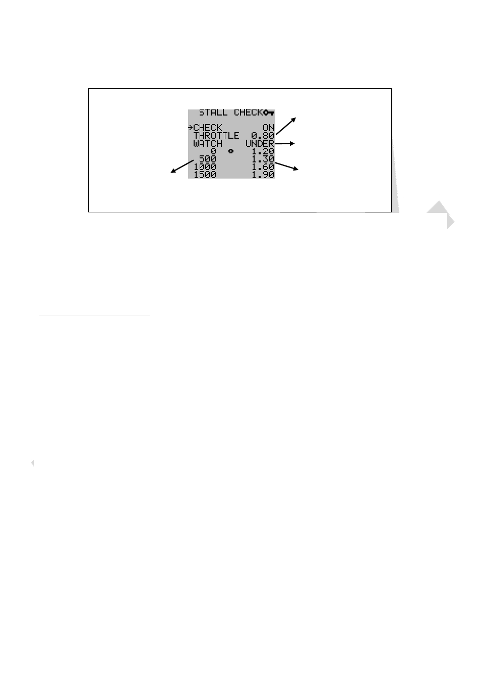
RPM
Restriction setting
Direction of monitored
throttle voltage
Set throttle voltage
Stall Check screen
Airflow output
voltage value
① It becomes effective only when equipped with the R-VIT, and set to communicate the throttle voltage through
the optical COM. It cannot be set on sensors other than the hot wire type.
② It sets the maximum value of the airflow output and the voltage on throttles that generates air blowbacks. If
the voltage becomes in the range of the set throttle voltage, it will control not to go beyond the maximum
output of the airflow voltage.
③ The setting methods on the RPM and preset value are the same as the TACHO MAP.
Example of the setting method.
21
(Refer to the above figure)
1. Activation or Inactivation Setup of Engine Stall Prevention.
ON/OFF is chosen at the CHECK item. In this case, it is ON.
2. Setup of Throttle Voltage.
Please check the throttle voltage at the time of Accelerator OFF by the monitoring of R-VIT or R-FIT. If the
voltage reading is 0.6V, instead of inputting the same value, input a slightly larger number such as 0.8V.
3. Monitoring Direction Setup of Throttle Voltage.
It is used to setup the direction to restrict the monitored voltage based on the voltage that was set at the
“Setup of Throttle Voltage”. (To restrict the voltage in a case it is lower or higher)
In this case, since the voltage was set a little higher than the actual voltage, it is chosen to restrict the voltage
lower than the set voltage. Therefore, UNDER is chosen to restrict the direction of the voltage.
4. Setup of RPM Restriction
It can be setup by every 100rpm by four points. Please set up the RPM so that the location (RPM) where the
stall occurs is in between the set RPM. In this case, it is set up every 500rpm, from 0rpm to 1500rpm.
5. Setup of Airflow Maximum Output Value
Input the airflow voltage that was set at the “ Setup of RPM Restriction” monitored by the R-FIT or R-VIT. (The
Airflow voltage at the time of IGN-ON is inputted at the time of 0rpm.)
In this case, make sure to perform the monitoring immediately after starting the engine (before it gets warm)
Moreover, please input a slightly higher value than the actual Airflow voltage value.
For example, when the output voltage is 1.52V, a value slightly higher such as 1.55V is inputted.
※The value inputted here is just an upper limit value. It is to control the output not to go beyond this value and
it does not need to be necessarily fixed to this value. Moreover, even if a stall happens after this function is
setup, please use the monitored value of the throttle voltage and airflow voltage as a reference to carry out
the setup of this function.
Online Manual Not For Resale Purposes
Online Manual Not For Resale Purposes
Online Manual Not For Resale Purposes
Online Manual Not For Resale Purposes
Online Manual Not For Resale Purposes
Online Manual Not For Resale Purposes
Online Manual Not For Resale Purposes
Online Manual Not For Resale Purposes
Online Manual Not For Resale Purposes
Online Manual Not For Resale Purposes
Online Manual Not For Resale Purposes
Online Manual Not For Resale Purposes
Online Manual Not For Resale Purposes
Online Manual Not For Resale Purposes
Online Manual Not For Resale Purposes
Online Manual Not For Resale Purposes
Online Manual Not For Resale Purposes
Online Manual Not For Resale Purposes
Online Manual Not For Resale Purposes
Online Manual Not For Resale Purposes
Online Manual Not For Resale Purposes
Online Manual Not For Resale Purposes
Online Manual Not For Resale Purposes
Online Manual Not For Resale Purposes