BASELINE Robo-Assist Accessory Kit 85607617 User Manual
Page 6
6 •
Tire Changers
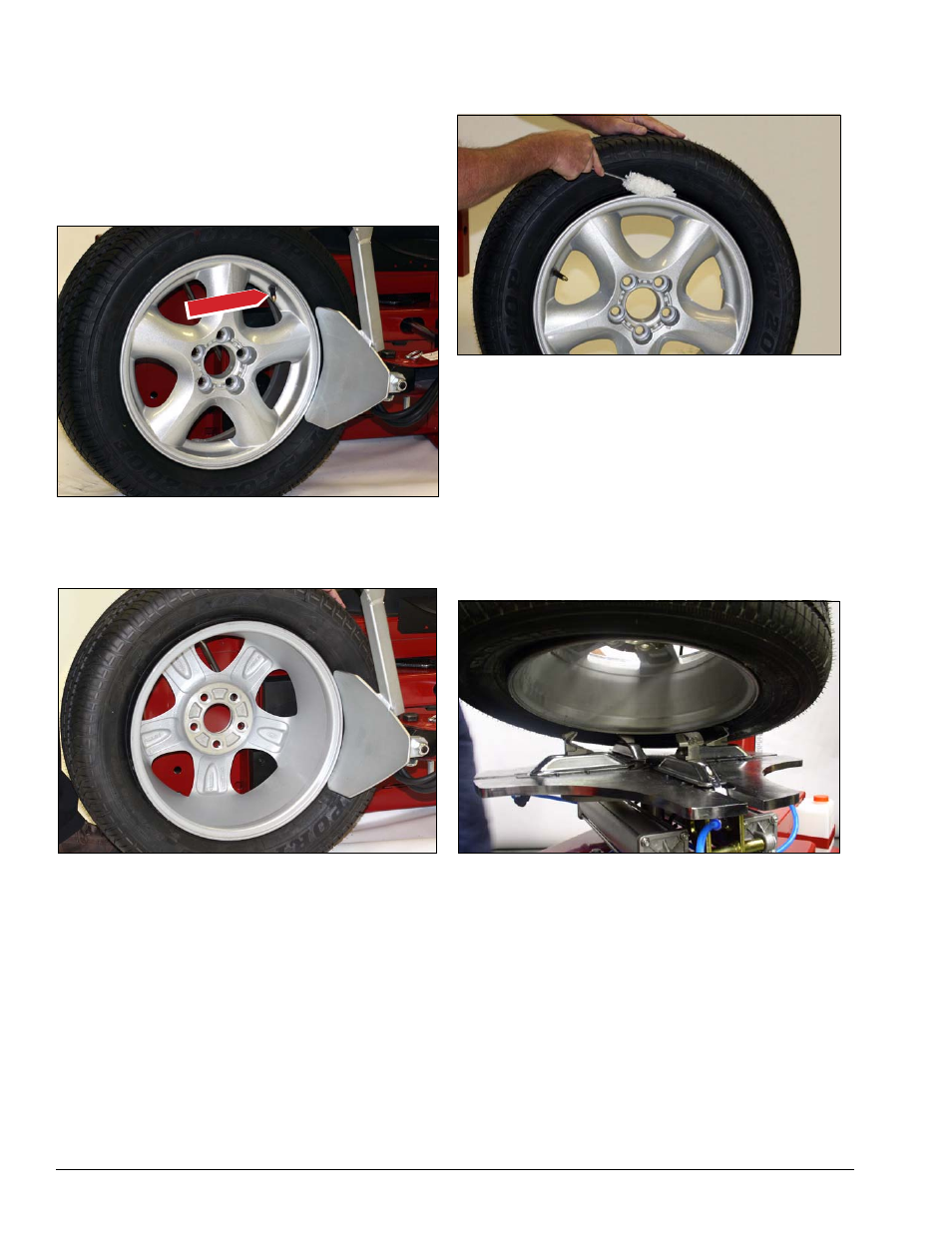
2.
Pull the bead loosener shoe away from the machine
and roll wheel into position. The valve stem should be
in the 2 o’clock position to accommodate a possible
asymmetric safety hump type rim. Position the bead
loosener shoe against the tire next to, but not on, the
rim. Press the bead loosener foot pedal to actuate the
shoe and loosen the bead. It may be necessary to
loosen the bead in multiple locations around the tire
(figure 3).
Figure 3 - Position Tire and Bead Loosener Shoe
3.
Turn the wheel around and repeat loosening pro-
cedure on the other side of the wheel (figure 4). This
should be the long side of the drop center (figure 2).
Figure 4 - Position Tire and Bead Loosener Shoe With Wheel
Turned Around
G. It will be easier to outside clamp the wheel to
the table top if the long side of the rim is loosened
last.
4.
Apply tire manufacturer’s approved rubber lubricant
liberally to entire circumference of both tire beads after
loosening (figure 5).
Figure 5 - Apply Rubber Lubricant to Tire Beads
5.
Determine the mounting side of the wheel. The
mounting side is the narrow side of the drop center. See
figure 2 for more information on the drop center.
6.
Place tire/wheel assembly on table top with mount-
ing side up (figure 6). Use the clamp control pedal to
move the clamps inward (push pedal down) or outward
(toggle pedal up). Clamp steel wheels from the inside
(clamps push outward against wheel). Clamp mag and
custom wheels from the outside (clamps push inward
against the outside rim edge).
Figure 6 - Place Tire/Wheel Assembly on Table top
Valve Stem