BASELINE Robo-Assist Accessory Kit 85607617 User Manual
Page 3
Tire Changers
• 3
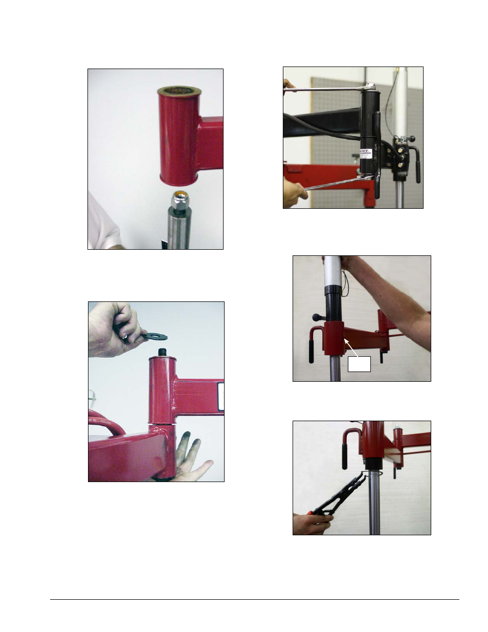
6.
Locate arm with valve assembly, install the 10 1/2-
inch (267 mm) long bolt with head through the bottom
side, slide pivot pin over bolt and attach nut with only
one turn.
Figure 6 - Locate and position arm with cylinder.
7.
Slide the cylinder arm pivot pin through the swing
arm bushing, hold in position, remove nut and place
washer over bolt threads and assemble nut to bolt.
Figure 7 - Hold swing arm in position to install nut to bolt
8.
Next, using large wrenches, tighten the assembly
to 240 ft. pound torque (very tight). Again, even though
the bolt is very tight, the assembly should be free to
rotate.
Figure 8 - Tighten the swing arm bolt.
9.
Slide the cylinder through the cylinder arm bush-
ing, aligning the cylinder for set screw installation.
Tighten the set screw.
Figure 9 - Slide cylinder through cylinder arm bushing.
10.
Install the external snap ring.
Figure 10 - Install external snap ring.
Set
Screw