Barranca Diamond GP-6 Cabmaker User Manual
Page 19
19
GP6 CABMAKER (PADS) MODEL
The GP6 Cabmaker (Pads) model is identical to the GP6 Cabmaker (Belts) in that both models use
4" diamond resin belts with an expandable rubber drum to sand and polish gemstone material. The
GP6 Cabmaker (Pads) model however, incorporates an additional feature that includes a 5" rubber
and rigid backer (and resin pad set) that mounts on to the right end of the shaft and uses a Loc-Line
flexible water nozzle and magnetic manifold with submersible pump to direct cooling water to the pads
(Fig 26). This feature of the Pads model enables the user to polish flat gemstone material across the
face of the 5" resin diamond pads by changing pads (grit sizes) with the easy to remove hook and look
material on the vertically mounted backer pad. The expandable drum is mounted on the left side of
the GP6 (Pads) model as opposed to the GP6 (Belts) which is mounted on the right end of the shaft.
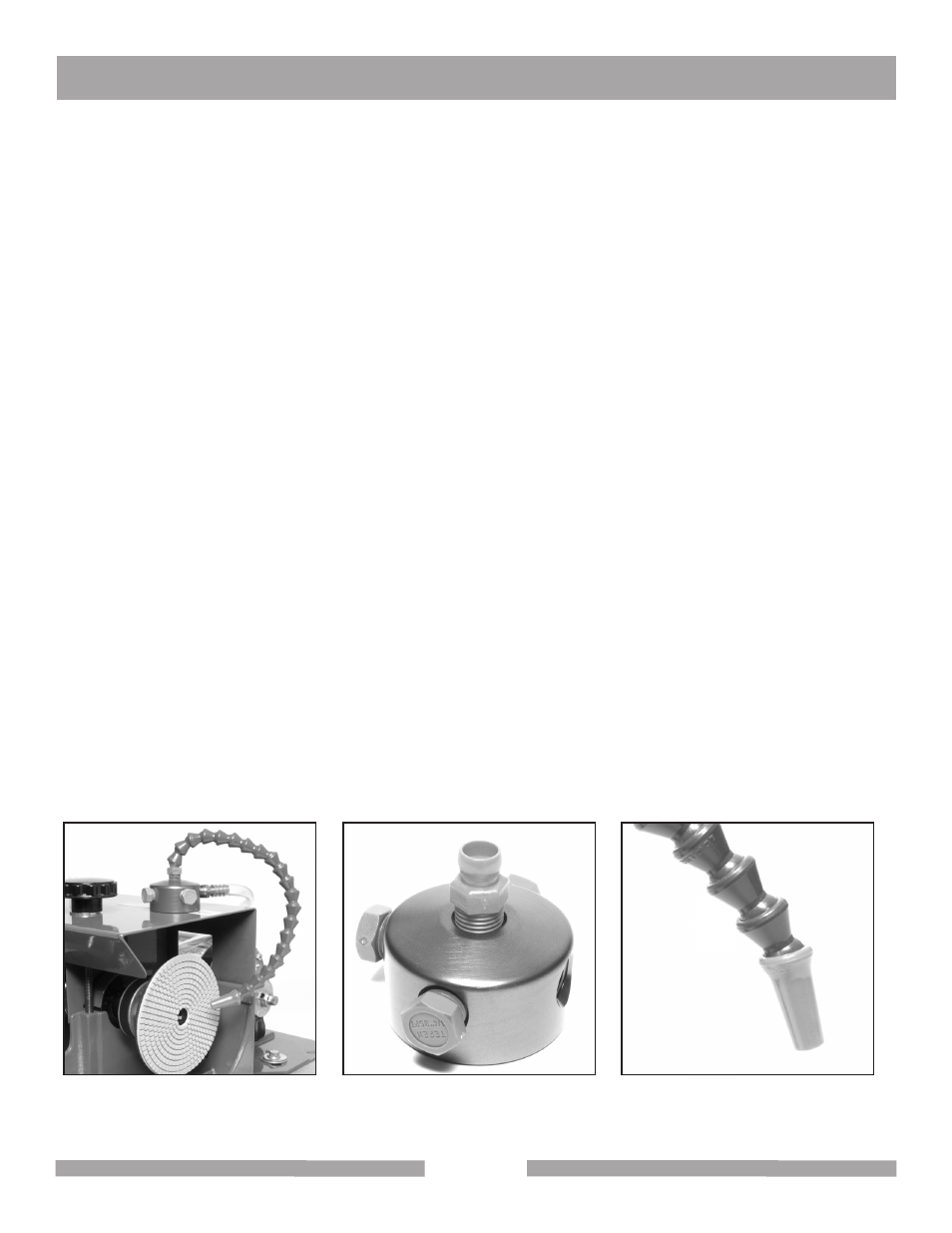
SET UP OF LOC LINE SYSTEM ON GP6 CABMAKER (PADS)
Remove the magnetic base manifold from its box and install (thread) the orange mounting connector
to the manifold (Fig 25). The blue loc line links will need to be affixed to the manifold connector and
small orange nozzle tip as well. Follow the instructions on the back of the Loc Line packaging. The
blue flexible line sections will connect to the orange connectors and nozzle tip (Fig 26) by forcing the
links together. If a vise is available use it to hold the orange nozzle while tapping the link segments
together with a mallet. Once assembled, the Loc Line magnetic manifold will need to have the brass
barb male bib threaded into its base (Fig 27) and the 1/2" OD clear tubing attached to the barb. The
3/8" OD clear tubing from the submersible pump inserted into the other end of the 1/2" OD clear tub-
ing.
The magnetic base manifold should be positioned on the metal hood of the GP6 unit adjacent to the
far right end closest to the right end of the shaft. This position will allow for the direction of water flow
to the 5" resin diamond pads during use (Fig 24). A flow restrictor (white clamp) should be installed
on the 3/8" diameter tubing near the junction of the water tube into the 1/2" OD tubing (Fig 28), so that
the user can restrict flow to a slow, steady drip to the center of the 5" resin diamond pads. Should the
customer want more precise flow control of the water to the pads, a brass T-valve can be installed in
the base manifold (not included with the GP6 [Pads]).
Fig 24
Fig 25
Fig 26
GP-6 CABMAKER
OPERATION AND ADJUSTMENT