Flame and burner adjustments – Bakers Pride 616 Manual User Manual
Page 14
14
FLAME AND BURNER ADJUSTMENTS
GAS PRESSURE ADJUSTMENTS
Baker’s Pride ovens are equipped with fixed sized ori-
fices. Adjustments can not be made to the orifice.
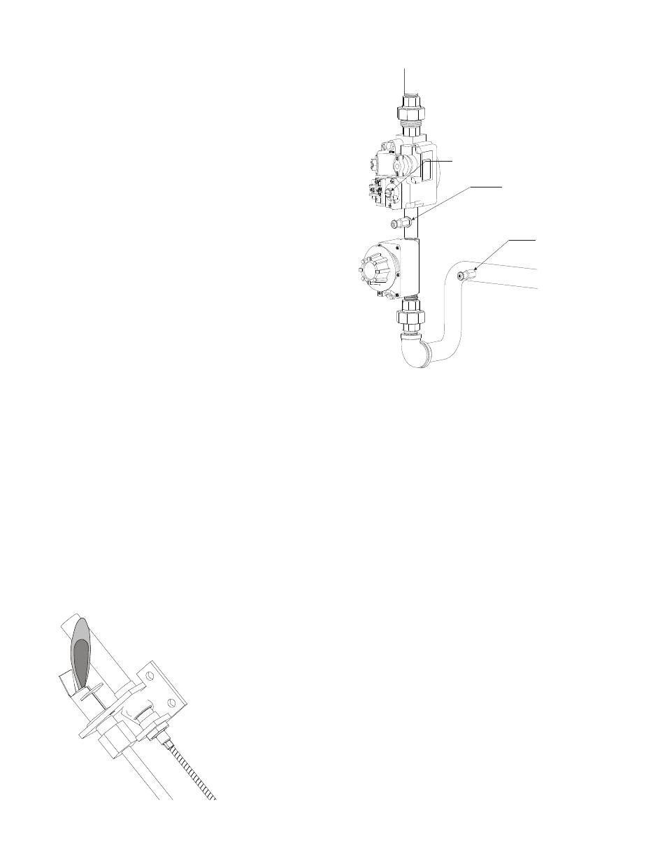
Gas flow and pressure is to be checked at installation.
A pressure tap is supplied with each oven. It is located
in the control compartment along the gas supply piping.
On older models this tap will be along the manifold
pipe or fittings. On newer models the pressure tap will
be located between the gas valve and thermostat.
Gas supply pressure must match the oven’s rating plate.
This value must be checked with the oven and all other
appliances on the same gas supply line running at their
highest burner setting.
Connect a manometer to the pressure tap and check the
gas pressure while the burners are running at their high-
est setting. Ovens equipped with a 7000 combination
valve have an adjustment screw on the front of the valve. Ovens equipped with a pilot safety valve will
have a traditional regulator in the gas line before the valve.
This adjustment is originally made at the factory prior to shipment. However, it must be re-checked
and/or adjusted at installation to match your gas supply. This adjustment is not covered by warranty.
PILOT LIGHTING AND ADJUSTMENTS
Most ovens have a combination valve that supplies gas to the pilot burner. Some ovens have a pilot
safety valve. The basic method is the same for each.
The 7000 combination valve has a dial that controls the gas flow. Turn it to “PILOT”. The pilot safety
valve has a RED button.
Turn the gas supply to the oven ON.
Slightly depress and turn the combination gas cock knob to the PILOT position.
Depress the dial or the red button and hold. It may take several minutes to bleed air from the tubing
supplying gas to the pilot burner.
Apply a flame to the pilot burner to light. Continue to hold the dial/button depressed for at least 30
seconds for the flame to be sensed by the valve.
After letting go of the dial/button if the pilot flame goes out repeat the
above steps.
Once the flame is lit and burning normally for several minutes to insure
all air is bled from the supply tube the flame may need to be adjusted.
On pilot safety valves there is an adjustment screw above the red button.
On combination valves there is an adjustment screw at the top left corner
of the valve body. Remove the pilot adjustment cap.
Using a small flat blade screwdriver turn the screw counter-clockwise to
reduce the size of the flame. Turn the screw clockwise to increase the
size of the flame. The flame should be approximately 3/8 in to 1/2 in
high and wrap around the flame sensor bulb.
NEWER
LOCATION
TRADITIONAL
LOCATION
ADJUSTMENT
SCREW