APG DCR-WEB user manual User Manual
Page 16
DCR-WEB
Rev. A3, 10/08
16
Automation Products Group, Inc.
APG...Providing tailored solutions for measurement applications
Tel: 1/888/525-7300 • Fax: 1/435/753-7490 • www.apgsensors.com • [email protected]
Calibration
Analog
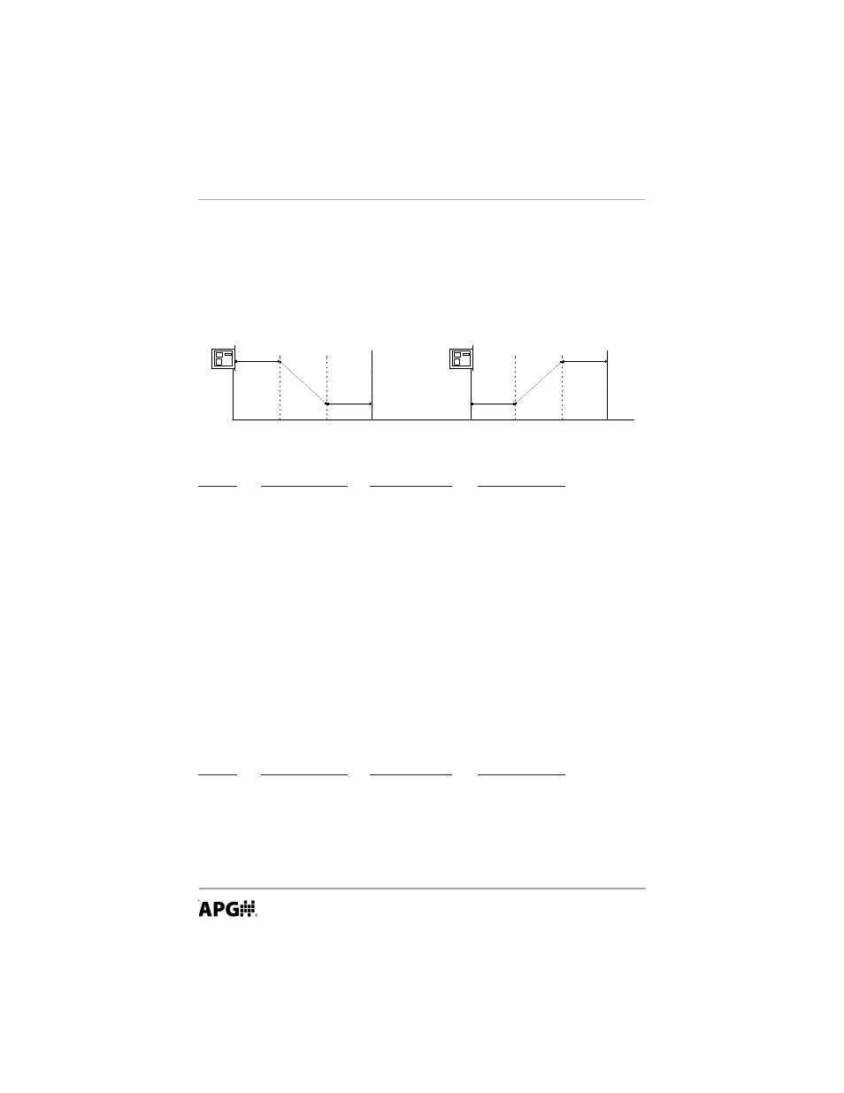
The DCR-WEB has an Isolated 0-10 V output. To set up this feature, enter the
two end points. If the level is beyond the bounds of the window created by the
two end points the voltage level will stay at the voltage level of the point it is
nearest to. Refer to the diagram below.
MODE
DESCRIPTION
PARAMETERS
EXPLANATION
0V DIST
0 V Distance
Units = inches
Default = 24.0
10V DIST 10 V Distance
Units = inches
Default = 48.0
The sensor can be programmed to any maximum voltage desired from 1 to 10.45
VDC. The calibration numbers are used to set the maximum and minimum voltage levels
of the analog slope. In most cases the minimum voltage is desired to be 0 so the value
for 0 V CAL mode is set to 0. However, if it was desired to have the minimum voltage
be 1.0 volts the value of this mode would be set to 4095(1)/10.45=391. The same is true
for the maximum voltage levels. If the maximum voltage is to be 6 VDC then 4095(6.0)/
10.45=2351 would be entered into the 10 V CAL mode.
MODE
DESCRIPTION
PARAMETERS
EXPLANATION
0V CAL
0 V Calibration
Units = 0-4095
10V CAL
10 V Calibration
Units = 0-4095
2351 = 6 VDC
3919 = 10 VDC
1 0 V D C
0 VDC 0 VDC
1 0 V D C
D i s t a n c e
0 V
D i s t a n c e
1 0 V
D i s t a n c e
0 V
D i s t a n c e
1 0 V
M a x . D i s t a n c e
Zero Point
M a x . D i s t a n c e
Zero Point
Sets the distance where the 0 V
point of the analog slope will
begin.
Sets the distance for the
maximum voltage of the analog
output slope.
Distance from transducer to the
floor.
Adjusts the minimum voltage on
the analog output.
Adjusts the maximum voltage
on the analog output.