Anchor FIESTA MARQUEE STAIR STEP KIT User Manual
Page 3
INSTALLING FABRIC
GUYING OFF THE FRAME
15. Prior to installing the upright legs under the frame, stakes should be driven and guy ropes attached. Consult the standard
Fiesta Marquee Installation Instructions for correct stake location and guying pattern.
CAUTION: Be sure the frame is guyed and stabilized before installing the fabric.
16. Consult the standard Fiesta Marquee Installation Instructions for fabric installation instructions. The fabric sections for the
ascending and descending angled sections will install in a similar fashiong and velcro to the standard fabric top sections.
RAISING THE FRAME
Raising the Top Level (See Fig.10)
CAUTION
:
A. Adjust guy rope tension selectively to protect against the wind until each section is raised and safely guyed.
B. Be sure to allow enough time and crew size to complete and secure the entire unit.
C. Alway raise the “downwind” sides first to prevent the wind from getting under the unit and lifting it beyond control.
D. Before raising the frame, go back and pin all Long Adapter Assemblies to lock in the adjustability of the splices.
17. At the Long Adapter Assembly (in the ridge), choose the most nearly aligned hole of the Long Insert
and replace the pin to lock out further adjustment of the splice insertion and secure the connection.
18. Raise the Top Level first. Insert legs under the “downwind” side, and then the “upwind” side,
selectively loosening and tightening guy ropes throughout the whole frame, as needed for wind.
19. Properly align the legs and re-tighten the guy ropes according to standard Fiesta Marquee Installation
Instructions.
Raising the Lower Level (See Fig.11)
20. At the Long Adapter Assemblies (in the eave), choose the closest hole of the Long Insert and replace
the pin to lock out further adjustment of the splice insertion and secure the connection.
21. Raise the Lower Level next, again inserting legs under “downwind” side and then the “upwind” side.
22. To raise this Top level, selectively loosen guy ropes, as needed. Safely tighten guy ropes.
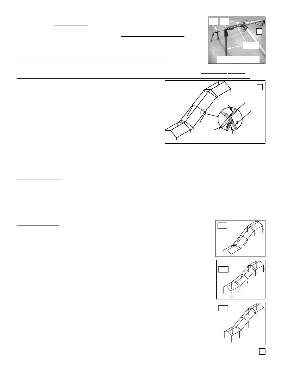
Raising the Inclined Section (See Fig.12)
23. To finish the installation, finish pushing the intermediate uprights (legs) to vertical and secure. Loosen
and re-tighten guy ropes, as needed.
24. Using a 1/4” Allen Wrench, tighten the rotation screw (See fig.4) in each Adjustable Elbow (in all
sections of the frame) to secure the hinges at the correct angle for the slope of the stairway or incline.
CAUTION: Before leaving the site, be sure all fabric is properly secured and all guy ropes
are uniformly tensioned according to the standard instructions for the Fiesta Marquee.
10
12
Adjustable
Inserts
Adapter Splices aligned for
up and down vertical swings.
Constructing the Lower Level with the Ascending Angle (See Fig.7):
Ridge
Pin.
Eave
Pin.
7. AT the Ridge Casting, pull the pin and install a Long Adaptor Assembly with holes aligned at a 90
degree angle. Leave the pin out at this connection until the overall inclined frame is completed.
This will allow easy adjustment to the angle of the incline.
8. At the opposite eave, repeat steps 1 and 2 above. Be sure to pin this eave adapter.
9 . Check to see that all (3) adapter assemblies rotate freely in a vertical direction and tighten the
splices into the Adjustable Elbows, using a 5/16” Allen Wrench (see Fig.9).
10. Insert and pin standard Fiesta Marquee rafters from eave to peak to eave to complete the angle.
Constructing the Inclined Section of Framing
12. Insert Eave and Ridge bars into the available locations of the Descending
Angle and pin.
13. Insert the opposite ends of these same Eave and Ridge Bars into standard
PTI castings and construct the rafter for the inclined section. Slide Upright
Adapter Assemblies onto the PTI splice and pin uprights to these assem
blies (See the inset in Fig.9). Let the uprights hinge forward down the
incline until later when the frame will be raised.
14. Install another set of standard Eave and Ridge Bars between the incline
uprights and the Lower Level (see fig. 1) on page 1. If necessary, adjust
the Long Adapter Assembly splices at the eaves of the Lower Level.
8
9
3
EAVE BAR
EAVE BAR
PTI
CASTING
PTI SPLICE
Slip the Upright Adapter Assembly up over the
PTI Splice, adjust to appropriate level & tighten.
11. For the Lower Level and the Ascending Angle, repeat Steps 1 through 7 above in reverse, using (2) Long Adapter Assemblies at
the eaves and (1) Short Adapter Assembly at the ridge. Pin the Short Adapter Assemblies, but Leave Long Adapter
Assemblies unpinned for easy adjusment to the proper angle when the inclined frame is being assembled (below).
NOTE: If the stairway is long enough to require additional units, you will need (1) additional Kit #8090691for each pair of uprights.
11