Caution – Anchor NAVI-TRAC FRAME LIFT User Manual
Page 2
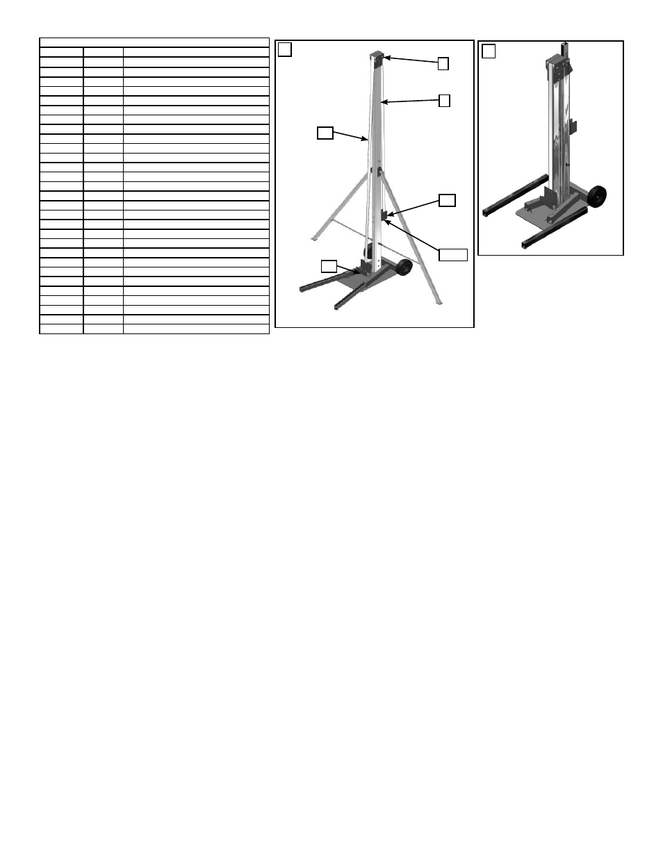
3
24
25,26
7
28
27
E
The Top Post can be stored on
the front splice stub of the base
plate when not in use.
F
Thank you for purchasing an Anchor product. In return, we pledge quality, service and craftsmanship and are available for
any questions you may have or assistance you may need.
Phone Number
(812) 867-2421
Fax Number
(812) 867-0547
Anchor products are of superior design and operate best within the parameters of these instructions. It is imperative that
the instructions be carefully read and completely followed. Please read assembly instructions before the use of this prod-
uct. Because this product may be used on a variety of Anchor tent products, you should also read the installation instruc-
tions for the specific tent with which this tool is to be used. Tent installation instructions are available at: www.anchorinc.
com.
CAUTION:
1. Use for installation of framed tent products only. Read relevant tent installation instructions.
2, Never exceed the maximum operating load stated within these instructions. Excess load may cause premature failure
and could result in serious personal injury.
3. Do not oil or grease the brake mechanism of this frame lift.
4. Never apply load to winch with web fully extended. Keep at least three full turns of web on the reel at all times.
5. During use, be sure web is neither twisted nor wrapped around the pole.
6. Follow instructions carefully, paying particular attention to all safety or cautionary comments.
Proper safety equipment should be used at all times to insure a safe operation. We suggest a careful evaluation be made
to determine safety equipment needed, such as hard hats, steel-toe shoes, safety glasses and other as required.
Disclaimer - Anchor Industries disclaims and excludes all express or implied warranties of
merchantability and and fitness for a particular purpose. The product is sold “as is” and no warranty shall apply. The user
shall determine the suitability of the product for the intended use and assumes all risk and liability. Anchor Industries shall
not be liable in tort or in contract for any loss or damage, direct, incidental or consequential arising out of the use of or the
inability to use the product.
FL12-00
PART LIST
ITEM #
QTY
DESCRIPTION
1
1
BASE WELDMENT
2
2
LEG INSERT
3
1
WEB GUIDE TOP WELDMENT
4
2
BRACE WELDMENT
5
1
BOTTOM POST
6
1
SPLICE TOP POST
7
1
TOP POST
8
2
HINGE FOR BRACE
9
3
1/2” x 3” HEX HD CAP SCREW
10
3
1/2” ST’D NC NYLOCK NUT
11
2
1” POLYPRO WEB
12
1
1/2” x 3 1/4” EYE BOLT
13
1
1/2” EYE NUT
14
2
1/2” x 3 1/4” FAS PIN
15
3
1/2” x 2 3/4” TENSION LOCK PIN
16
2
1/2”-13 x 3 1/4” HEX HD CAP SCREW
17
2
1/2”-13 NYLOCK JAM NUT
18
2
SNAP
19
4
#10 FENDER WASHER
20
4
1” x #10 TEC SCREW
21
2
3 1/2” x 10 1/2” DIA. TURF WHEEL
22
2
1/2”-13 x 5” HEX HD CAP SCREW
23
2
1/2”-13 HEX NUT
24
1
WINCH ASSEMBLY
25
2
3/8”-16 x 5 1/2” HEX HD CAP SCREW
26
2
3/8”-16 UNC HEX NUT
27
1
EAVE HOOK
28
25’-6”
1 1/2” POLYESTER WEB